GOT3187W-881-PCT
User’s Manual
Hardware and Installation
13
2.3.4
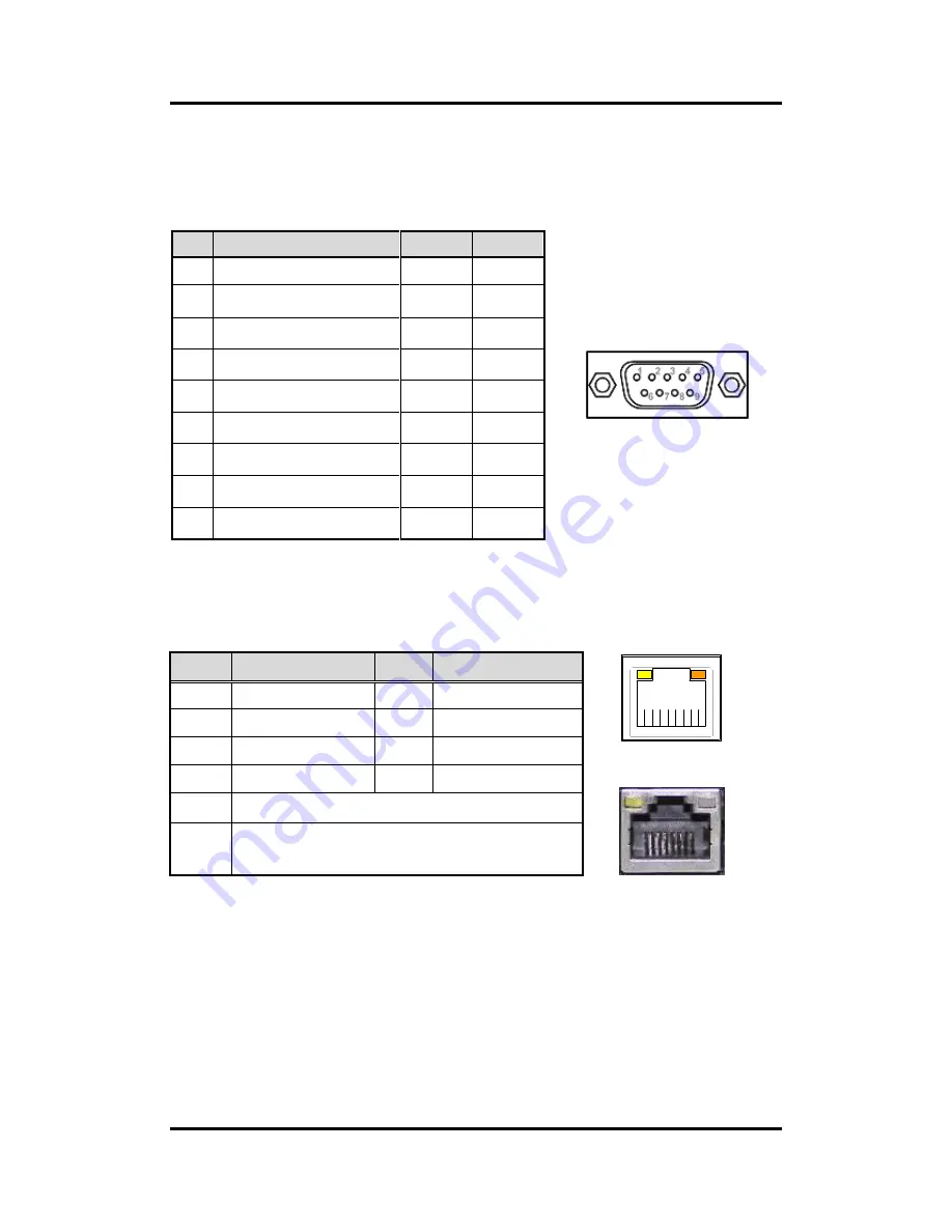
COM Serial Port Connector
The system has six serial ports. COM1/2 are RS-232/422/485 ports. Please refer to Chapter 3
for the detail of BIOS setting.
Pin
RS-232
RS-422
RS-485
COM1/2
1
DCD, Data Carrier Detect
TX-
Data-
2
RXD, Receive Data
TX+
Data+
3
TXD, Transmit Data
RX+
No use
4
DTR, Data Terminal Ready
RX-
No use
5
GND, Ground
No use
No use
6
DSR, Data Set Ready
No use
No use
7
RTS, Request To Send
No use
No use
8
CTS, Clear To Send
No use
No use
9
RI, Ring Indicator
No use
No use
2.3.5
Ethernet Connector
The RJ-45 connector is for Ethernet. To connect the board to a 1000/100/10 Base-T hub, just
plug one end of the cable into connector and connect the other end (phone jack) to a
1000/100/10-Base-T hub.
Pin
Signal
Pin
Signal
L1
L2
L3
L4
L5
L6
L7
L8
A
B
A
B
L1
MDI0+
L5
MDI2-
L2
MDI0-
L6
MDI1-
L3
MDI1+
L7
MDI3+
L4
MDI2+
L8
MDI3-
A
Active LED (Yellow)
B
100 LAN LED (Green)/ 1000 LAN LED (Orange)
Summary of Contents for GOT3187W-881-PCT
Page 1: ...GOT3187W 881 PCT All in One 18 5 WXGA TFT Fanless Multi Touch PANEL PC User s Manual ...
Page 6: ...vi This page is intentionally left blank ...
Page 40: ...GOT3187W 881 PCT User s Manual 34 AMI BIOS Utility XCHI Hand off EHCI Hand off ...
Page 44: ...GOT3187W 881 PCT User s Manual 38 AMI BIOS Utility NCT6106D HW Monitor PC Health Status ...
Page 54: ...GOT3187W 881 PCT User s Manual 48 AMI BIOS Utility This page is intentionally left blank ...


