background image

IPC950 use

r’s Manual 


AMI BIOS Utility 

59


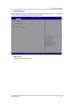
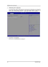
USB Configuration 

USB configuration can be configured here by selecting and changing each item. A description 
of the selected item appears on the right side of the screen.


USB Devices 

Display all detected USB devices. 


Summary of Contents for IPC950

Page 1: ...IPC950 Industrial Computers User s Manual...

Page 2: ...efulness of any information in this document Axiomtek does not make any commitment to update the information in this manual Axiomtek reserves the right to change or revise this document and or product...

Page 3: ...voltage of the power source is correct before connecting the equipment to the power outlet 5 Turn OFF the system power before cleaning Clean the system using a cloth only Do not spray any liquid clea...

Page 4: ...lean any single part or component for the computer please read and understand the details below fully When you need to clean the device please rub it with a piece of dry cloth 1 Be cautious of the tin...

Page 5: ...cloth a bit with some water or rubbing alcohol and rub it on the computer Unknown solvents may be harmful to the plastics parts Vacuum cleaner Vacuuming the dust dirt hair cigarette particles and oth...

Page 6: ...in case computers are out of order or are no longer in use Trademark Acknowledgments Axiomtek is a trademark of Axiomtek Co Ltd Intel and Pentium are registered trademarks of Intel Corporation Window...

Page 7: ...nector 24 1 8 9 AT ATX Switch 24 1 8 10 Digital I O Connector 24 1 8 11 Front Panel LED 25 1 8 12 SATA Connector 25 1 8 13 SATA Power Connector 25 1 8 14 SIM Card Slot 26 1 8 15 Full Size PCI Express...

Page 8: ...arting 49 3 2 Navigation Keys 50 3 3 Main Menu 51 3 4 Advanced Menu 52 3 5 Chipset Menu 64 3 6 Security Menu 65 3 7 Boot Menu 67 3 8 Save Exit Menu 68 APPENDIX A WATCHDOG TIMER 71 A 1 About Watchdog T...

Page 9: ...ions Dimensions I O Outlets Jumper Settings Connectors Package List 1 1 General Description The IPC950 is a fanless system that supports Intel 11th generation CoreTM i7 1185G7E i5 1145G7E i3 1115G4E C...

Page 10: ...bookshelf and wall mount 1 2 2 System I O Standard I O Interface Front One ATX power on off switch One ATX AT mode switch One 2 pin connector output for remote power on off switch DC to DC power supp...

Page 11: ...ta bits 1 parity bit even or odd 2 stop bits Two DP 1 2 4K support resolution up to 4096 2160 60Hz One Audio Line out Expansion Interface Mini Card slot w SIM slot One on board full size PCI Express M...

Page 12: ...HDD SSD Note The performance of the system might be adversely affected when it is operating at a temperature above the system s limitation or with an unrecommended processor Note If the operating temp...

Page 13: ...IPC950 user s Manual Introduction 13 1 3 Dimensions The following diagrams show you the dimensions and outlines of the IPC950 IPC950 IPC950 w DIN rail 9...

Page 14: ...IPC950 user s Manual 14 Introduction IPC950 w bookshelf IPC950 w wall mount...

Page 15: ...IPC950 user s Manual Introduction 15 IPC950 w 1 PCIe x4 expansion kit IPC950 w 1 PCIe x4 expansion kit and DIN rail...

Page 16: ...IPC950 user s Manual 16 Introduction IPC950 w 1 PCIe x4 expansion kit and bookshelf IPC950 w 1 PCIe x4 expansion kit and wall mount...

Page 17: ...ets Mark Description 1 4 x LED 2 1 x RS 232 422 485 default RS 232 3 3 x LAN 4 1 x Line out 5 1 x Remote power switch 6 1 x Switch for power on off 7 3 x Antenna opening 8 8CH DIO 9 Flexible system I...

Page 18: ...ollowing items IPC950 unit x 1 Screw pack x 1 Terminal block x 1 Remote power switch cable x 1 Antenna plastic isolated washer x 3 If you cannot find this package or any items are missing please conta...

Page 19: ...OS Optimal Defaults Default Normal Operation Short 1 2 Note How to setup Jumpers The illustration shows how to set up jumpers When the jumper cap is placed on pins the jumper is closed if not that mea...

Page 20: ...Phoenix Power Connector 3 3 1 DisplayPort Connector 3 3 3 Serial Port Connector 3 3 4 USB 3 0 Connector 3 3 5 Ethernet Connector 3 3 6 Audio Connector 3 3 7 ATX Power On Off Button 3 3 8 Remote Power...

Page 21: ...DC 3 Chassis gnd 1 8 2 DisplayPort Connector The IPC950 supports two dual mode DP interfaces DP1 which support DP resolution up to 4096x2304 60Hz Pin Signal Pin Signal 1 DPB_LANE0 11 GND 2 GND 12 DPB...

Page 22: ...ach USB port is set to use standby power by default which can be enabled or disabled by GPIOs Pin Signal USB Port 0 Pin Signal USB Port 1 1 USB_VCC 5V level standby power 10 USB_VCC 5V level standby p...

Page 23: ...ine Out Pin Signal 1 Line Out 1 8 7 ATX Power On OFF Button The system has one ATX power button on the I O side that allows users to control the IPC950 s power on off state Function Description On Tur...

Page 24: ...by setting the AT ATX switch to AT mode Auto power on feature can be achieved by setting this switch 1 8 10 Digital I O Connector The IPC950 is equipped with an 8 channel digital I O connector that me...

Page 25: ...erted and solid red while THERMTRIP is asserted on CPU LED 1 8 12 SATA Connector The IPC950 has one Serial Advanced Technology Attachment Serial ATA or SATA 3 0 port CN11 with 6Gb s performance This i...

Page 26: ...Express and USB 2 0 signals and complies with PCI Express Mini card specification version 1 2 Pin Signal Pin Signal 1 WAKE 2 3 3VSB 3 No use 4 GND 5 No use 6 1 5V 7 CLKREQ 8 No use 9 GND 10 No use 11...

Page 27: ...ard mouse scanner etc 1 8 17 M 2 B M KEY 2280 Connector SCN1 The IPC950 provides one M 2 B M key 2280 connector SCN1 which supports Serial Advanced Technology Attachment Serial ATA or SATA 3 0 port in...

Page 28: ...se 36 No use 37 No use 38 DEVSLP1 39 GND 40 No use 41 SATA1_RXP 42 No use 43 SATA1_RXN 44 No use 45 GND 46 No use 47 SATA1_TXN 48 No use 49 SATA1_TXP 50 No use 51 GND 52 No use 53 No use 54 No use 55...

Page 29: ...10 M2_SATA_LED 11 No use 12 No use 13 GND 14 No use 15 No use 16 No use 17 No use 18 GND 19 GND 20 UART_WAKE 21 No use 22 UART_TXD 23 No use 24 25 26 27 28 29 30 31 32 UART_RXD 33 GND 34 UART_RTS 35...

Page 30: ...485 ports RS 232 422 485 can be configured via BIOS settings COM2 COM3 COM4 COM5 Pins RS 232 RS 422 RS 485 1 DCD Data Carrier Detect TX Data 2 RXD Receive Data TX Data 3 TXD Transmit Data RX No use 4...

Page 31: ...ier Detect TX Data 2 RXD Receive Data TX Data 3 TXD Transmit Data RX No use 4 DTR Data Terminal Ready RX No use 5 GND Ground No use No use 6 DSR Data Set Ready No use No use 7 RTS Request To Send No u...

Page 32: ...digital input channels accepts 0 30 VDC with sink type and source type Isolated Digital Output The figure shows how to connect between an output channel and the system If an external voltage 5 30 VDC...

Page 33: ...to Chapter 4 for the details of BIOS settings COM2 COM3 COM4 COM5 Pins RS 232 RS 422 RS 485 1 DCD Data Carrier Detect TX Data 2 RXD Receive Data TX Data 3 TXD Transmit Data RX No use 4 DTR Data Termin...

Page 34: ...Gigabit LAN Please refer to Chapter 4 for the details of BIOS settings AX93519 2 x RS232 422 485 1 GE LAN i211AT 2 USB 2 0 Pins Signal USB Port 0 Pins Signal USB Port 1 1 USB_VCC 5V level standby powe...

Page 35: ...al Ready RX No use 5 GND Ground No use No use 6 DSR Data Set Ready No use No use 7 RTS Request To Send No use No use 8 CTS Clear To Send No use No use 9 RI Ring Indicator No use No use Pins 1000 Base...

Page 36: ...IPC950 user s Manual 36 Introduction This page is intentionally left blank...

Page 37: ...module HDD Hard Disk Drive and PCIe card Chapter 2 will show you how to install these hardware parts Procedure of Installation Step 1 Turn off the system Step 2 Disconnect the power connector Step 3...

Page 38: ...The socket latches are clipped onto the edges of the memory module Step 3 After installing the memory modules screw the bracket and close the cover back to the chassis and fasten all screws 2 2 Insta...

Page 39: ...llation is complete 2 3 Installing the NVMe SSD The IPC950 offers a M 2 B M key socket for users to install NVMe SSD Please follow the steps to install Step 1 Loosen two screws and remove the bracket...

Page 40: ...alling the M 2 Key E Module The IPC950 offers an M 2 key E socket for users to install a wireless module When installing the wireless LAN card refer to the following instructions and illustration Step...

Page 41: ...her out of the accessory box Put a washer into an antenna cable Step 4 Connect the antenna cables to the wireless LAN card Step 5 The IPC950 supports three antenna openings please remove the antenna p...

Page 42: ...stration Step 1 Find the mini PCI socket in the main board then install the wireless module to the socket and screw a screw to fix it Note When installing a half size mini card please use the extended...

Page 43: ...ocedure of installing the flexible I O module into the system is instructed below Step 1 Loosen two screws and remove the blank I O cover Step 2 Find the flexible I O connector on the main board Align...

Page 44: ...kit into the system is instructed below Step 1 Loosen eight screws to remove the cover from the EIO110 expansion box kit Step 2 Find the slot on the main board Align the EIO110 with the slot press th...

Page 45: ...The IPC950 provides a DIN rail kit a bookshelf bracket and a wall mount kit for optional selection DIN rail mount Step 1 Screws the below two parts together with seven screws Step 2 Fasten the DIN rai...

Page 46: ...ardware Installation Bookshelf mount Step 3 Fasten the book shelf bracket to the chassis with four screws Installation is complete Wall mount Step 4 Fasten the wall mount kit to the chassis with four...

Page 47: ...IPC950 user s Manual Hardware Installation 47 Screw...

Page 48: ...IPC950 series user s manual 48 Hardware Installation This page is intentionally left blank...

Page 49: ...o enter the setup screens follow the steps below 1 Turn on the computer and press the Del key immediately 2 After you press the Del key the main BIOS setup menu displays You can access the other setup...

Page 50: ...en Plus Minus The Plus and Minus Arrow keys allow you to change the field value of a particular setup item Tab The Tab key allows you to select setup fields F1 The F1 key allows you to display the Gen...

Page 51: ...tab System Time Date can be set up as described below The Main BIOS setup screen is shown below System Date Time Use this option to change the system time and date Highlight System Time or System Dat...

Page 52: ...ity 3 4 Advanced Menu The Advanced menu allows users to configure the CPU and other system devices You can select any of the items in the left frame of the screen to go to the sub menus For items mark...

Page 53: ...IPC950 user s Manual AMI BIOS Utility 53 HW Monitor This screen monitors hardware health...

Page 54: ...IPC950 series user s manual 54 AMI BIOS Utility NCT7802Y HW Monitor This screen monitors the hardware health of the EIO110 PCIe x4 riser card...

Page 55: ...IPC950 user s Manual AMI BIOS Utility 55 Trusted Computing Select Security Device Support to enable or disable the TPM function...

Page 56: ...shows the CPU configuration where you can change the value of the selected option Intel Virtualization Technology This item allows a hardware platform to run multiple operating systems separately and...

Page 57: ...lity 57 SATA and RST Configuration You can read the current installed hardware configurations from those SATA ports in the SATA and RST Configuration menu During system boot up BIOS will detect the pr...

Page 58: ...IPC950 series user s manual 58 AMI BIOS Utility AMT Configuration Enable or disable Active Management Technology BIOS features The default is disabled...

Page 59: ...S Utility 59 USB Configuration USB configuration can be configured here by selecting and changing each item A description of the selected item appears on the right side of the screen USB Devices Displ...

Page 60: ...to select options for the Super IO Configuration and change the value of the selected option A description of the selected item appears on the right side of the screen For items marked with please pre...

Page 61: ...IPC950 user s Manual AMI BIOS Utility 61...

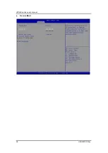
Page 62: ...C950 series user s manual 62 AMI BIOS Utility Serial Port Console Redirection This screen allows you to set serial port console redirection COM Port Type Use this item to set parameters of RS232 422 4...

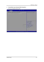
Page 63: ...IPC950 user s Manual AMI BIOS Utility 63 Compatibility Support Module CSM Configuration This screen displays CSM information...

Page 64: ...es user s manual 64 AMI BIOS Utility 3 5 Chipset Menu The Chipset menu allows users to change the advanced chipset settings You can select any of the items in the left frame of the screen to go to the...

Page 65: ...nu allows users to change the security settings for the system Administrator Password This item indicates whether an administrator password has been set installed or uninstalled User Password This ite...

Page 66: ...IPC950 series user s manual 66 AMI BIOS Utility Secure Boot...

Page 67: ...for setup activation key 65535 0xFFFF means indefinite waiting Bootup NumLock State Use this item to select the power on state for the keyboard NumLock Quiet Boot Select to display either POST output...

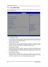
Page 68: ...ystem configuration and return to Main Menu Select Discard Changes and Exit from the Save Exit menu and press Enter Select Yes to discard changes and exit Save Changes and Reset When finishing the sys...

Page 69: ...Discard Changes from the Save Exit menu and press Enter Select Yes to discard changes Save as User Defaults Select this option to save your current system configuration settings as User Defaults Selec...

Page 70: ...IPC950 series user s manual 70 AMI BIOS Utility This page is intentionally left blank...

Page 71: ...initial value and must reset it periodically If the counter ever reaches zero which means the software has crashed the system will reboot A 2 How to Use Watchdog Timer The I O port base addresses of w...

Page 72: ...example to enable configuration using debug O 2E 87 O 2E 87 2 Select Logic device O 2E 07 O 2F 07 3 WDT Device Enable O 2E 30 O 2F 01 4 Activate WDT O 2E FA O 2F 01 5 Set base timer O 2E F6 O 2F 0A S...

Reviews: