IPC950 u
ser’s Manual
20
Introduction
1.8 Connectors
Connectors connect the board with other parts of the system. Loose or improper
connection might cause problems. Make sure all connectors are properly and firmly
connected. Here is a table summarizing all connectors and buttons on the
IPC950
series.
External Connectors
Section
DC-in Phoenix Power Connector
3.3.1
DisplayPort Connector
3.3.3
Serial Port Connector
3.3.4
USB 3.0 Connector
3.3.5
Ethernet Connector
3.3.6
Audio Connector
3.3.7
ATX Power On/Off Button
3.3.8
Remote Power Switch Connector
3.3.9
AT/ATX Switch
3.3.10
Digital I/O
3.3.11
Front Panel Connector
3.3.12
Internal Connectors
Section
Serial ATA (SATA) Connector
3.3.13
SATA Power Connector
3.3.14
SIM Card Slot
3.3.15
Full-Size Express Mini Card slot
3.3.16
USB 2.0 Connector
3.3.17
M.2 M key Connector (2280)
3.3.18
M.2 E key Connector (2242)
3.3.19
Summary of Contents for IPC950
Page 1: ...IPC950 Industrial Computers User s Manual...
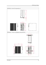
Page 14: ...IPC950 user s Manual 14 Introduction IPC950 w bookshelf IPC950 w wall mount...
Page 36: ...IPC950 user s Manual 36 Introduction This page is intentionally left blank...
Page 47: ...IPC950 user s Manual Hardware Installation 47 Screw...
Page 48: ...IPC950 series user s manual 48 Hardware Installation This page is intentionally left blank...
Page 53: ...IPC950 user s Manual AMI BIOS Utility 53 HW Monitor This screen monitors hardware health...
Page 61: ...IPC950 user s Manual AMI BIOS Utility 61...
Page 66: ...IPC950 series user s manual 66 AMI BIOS Utility Secure Boot...
Page 70: ...IPC950 series user s manual 70 AMI BIOS Utility This page is intentionally left blank...


