IPC950 u
ser’s Manual
24
Introduction
1.8.8 Remote Power Switch Connector
The remote power on/off feature can be achieved by using the 2-pin connector on the system
I/O side.
Function
Description
Short(1-2)
Turn on/off system
Open
Keep system status
1.8.9 AT/ATX Switch
The system can be automatically powered on without pressing the power button when power
input is supplied by setting the AT/ATX switch to AT mode. Auto power-on feature can be
achieved by setting this switch.
1.8.10 Digital I/O Connector
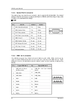
The IPC950 is equipped with an 8-channel digital I/O connector that meets
requirements for the system customary automation control. The digital I/O can be
configured to control cash drawers and sense warning signals from an Uninterrupted
Power System (UPS), or perform store security control. You may use software
programming to control these digital signals.
Pin
Signal
Pin
Signal
1
DIO1
6
DIO5
2
DIO2
7
DIO6
3
DIO3
8
DIO7
4
DIO4
9
DIO8
5
NA
10
GND
Summary of Contents for IPC950
Page 1: ...IPC950 Industrial Computers User s Manual...
Page 14: ...IPC950 user s Manual 14 Introduction IPC950 w bookshelf IPC950 w wall mount...
Page 36: ...IPC950 user s Manual 36 Introduction This page is intentionally left blank...
Page 47: ...IPC950 user s Manual Hardware Installation 47 Screw...
Page 48: ...IPC950 series user s manual 48 Hardware Installation This page is intentionally left blank...
Page 53: ...IPC950 user s Manual AMI BIOS Utility 53 HW Monitor This screen monitors hardware health...
Page 61: ...IPC950 user s Manual AMI BIOS Utility 61...
Page 66: ...IPC950 series user s manual 66 AMI BIOS Utility Secure Boot...
Page 70: ...IPC950 series user s manual 70 AMI BIOS Utility This page is intentionally left blank...


