background image

MANO831 Mini ITX Board


Introduction


1.4 

Block Diagram 


Summary of Contents for Mano831 Series

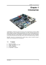
Page 1: ...MANO831 Series Intel AtomTM D2550 Mini ITX Motherboard User s Manual ...

Page 2: ...anual Axiomtek reserves the right to change or revise this document and or product at any time without notice No part of this document may be reproduced stored in a retrieval system or transmitted in any form or by any means electronic mechanical photocopying recording or otherwise without the prior written permission of Axiomtek Co Ltd CAUTION If you replace wrong batteries it causes the danger o...

Page 3: ...arges static electricity from your body Wear a wrist grounding strap available from most electronic component stores when handling boards and components Trademarks Acknowledgments Axiomtek is a trademark of Axiomtek Co Ltd Windows is a trademark of Microsoft Corporation AMI is a trademark of American Megatrend Inc IBM PC AT PS 2 VGA are trademarks of International Business Machines Corporation Int...

Page 4: ... used throughout this manual Warning Information to prevent injury to yourself when trying to complete a task Caution Information to prevent damage to the components when trying to complete a task Important Instructions that you MUST follow to complete a task Note Tips and additional information to help you complete a task ...

Page 5: ... Power Mode Selection JDS6 10 2 2 8 SATA Port 2 Function Selection JSATA_SEL1 10 2 2 9 System Deep S5 Power Saving Control JDS5 10 2 3 Connectors 11 2 3 1 Rear Panel Connectors 12 2 3 2 FAN Connectors CPU_FAN1 and SYS_FAN1 12 2 3 3 Front Panel Connector F_PANEL 13 2 3 4 ATX Power Connector ATX12V 14 2 3 5 Serial Connectors COM3 and COM4 14 2 3 6 Internal Audio Connector AAFP1 15 2 3 7 Digital Audi...

Page 6: ...sion Card 27 3 4 1 Installing an Expansion Card 27 3 4 2 Configuring an Expansion Card 28 3 4 3 PCI Slot 28 3 4 4 PCI Express Mini Card Connector 28 3 4 5 CompactFlash TM Socket 29 Chapter 4 Hardware Description 31 4 1 Microprocessors 31 4 2 BIOS 31 4 3 System Memory 31 4 4 I O Port Address Map 32 4 5 Interrupt Controller IRQ Map 34 4 6 Memory Map 37 Chapter 5 AMI BIOS Setup Utility 39 5 1 Startin...

Page 7: ... with two slots of single channel DDR3 memory at 1066 MHz supporting up to 4GB maximum With breakthrough low power silicon MANO831 can be used with a passive thermal solution based on the recommended boundary conditions MANO831 represents a fundamental shift in system design small yet powerful enough to enable a big internet experience for all audiences 1 1 Features Intel Atom TM D2550 2 DDR3 1066...

Page 8: ...wer One PS 2 keyboard mouse Serial ATA Two SATA 2 0 ports 3Gb s performance USB Interface Seven USB 2 0 ports Display One DVI One VGA Two LVDS Ethernet Two Realtek RTL8111E Gigabit LAN Audio HD audio compliant with MIC in line out line in and front audio header via Realtek ALC892 Expansion Interface One PCI slot One PCI Express Mini Card One CompactFlash TM socket Hardware Monitoring Monitoring te...

Page 9: ...3 Form Factor Mini ITX form factor Note All specifications and images are subject to change without notice 1 3 Utilities Supported Chipset driver Ethernet driver Graphics driver Audio driver TPM driver ME driver RAID driver USB3 0 driver ...

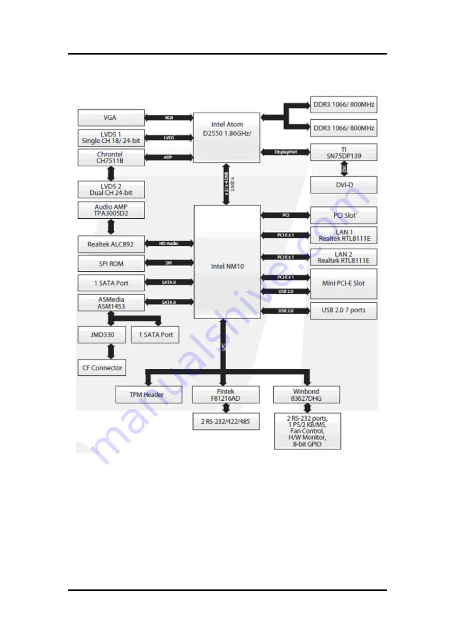
Page 10: ...MANO831 Mini ITX Board 4 Introduction 1 4 Block Diagram ...

Page 11: ...MANO831 Mini ITX Board Board and Pin Assignments 5 Chapter 2 Board and Pin Assignments 2 1 Board Layout Top View ...

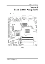
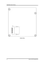
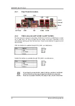
Page 12: ...MANO831 Mini ITX Board 6 Board and Pin Assignments Bottom View ...

Page 13: ...umper Description Setting JCMOS1 Clear CMOS Default Normal Operation 1 2 close JP1 COM3 RS 232 422 485 Mode Setting Default RS 232 Mode 1 3 2 4 close JP2 1 3 2 4 close JP3 1 2 close JP4 COM4 RS 232 422 485 Mode Setting Default RS 232 Mode 1 3 2 4 close JP5 1 2 close JP6 1 3 2 4 close JCOMPWR3 COM3 RI 5V 12V Selection Default RI 3 4 close JCOMPWR4 COM4 RI 5V 12V Selection Default RI 3 4 close JLVDS...

Page 14: ...r about 5 10 seconds then move the cap back to pins 1 2 4 Re install the battery 5 Plug the power cord and turn ON the computer 6 Hold down the Del key during the boot process and enter BIOS setup to re enter data Caution Except when clearing the RTC RAM never remove the cap on this jumper default position Removing the cap will cause system boot failure 2 2 2 COM3 RS 232 422 485 Mode Setting JP1 J...

Page 15: ... to select the power mode of COM port 4 2 2 6 LVDS Backlight Power Selection JLVDS_P1 This jumper allows you to select LVDS backlight power Function Setting RS 232 mode Default JP4 1 3 2 4 close JP5 1 2 close JP6 1 3 2 4 close RS 422 mode JP4 3 5 4 6 close JP5 3 4 close JP6 3 5 4 6 close RS 485 mode JP4 3 5 4 6 close JP5 5 6 close JP6 3 5 4 6 close Function Setting 12V 1 2 close RI Default 3 4 clo...

Page 16: ...elect AT mode or ATX mode 2 2 8 SATA Port 2 Function Selection JSATA_SEL1 2 2 9 System Deep S5 Power Saving Control JDS5 Function Setting AT mode 1 2 close ATX mode Default 2 3 close Function Setting CF 1 2 close SATA HDD Default 2 3 close Function Setting Deep S5 state 1 2 close Normal ACPI S5 state Default 2 3 close ...

Page 17: ...2_USB01 LAN2 and USB 2 0 Connector Audio1 Audio Jack SODIMM_1 204 pin DDR3 SO DIMM Slot 1 SODIMM_2 204 pin DDR3 SO DIMM Slot 2 PCI PCI Slot MINI CARD1 PCI Express Mini Card Connector CF1 CompactFlash TM Socket CPU_FAN1 CPU Fan Connector SYS_FAN1 System Fan Connector F_PANEL Front Panel Connector ATX12V ATX Power Connector COM3 COM4 Serial Connectors AAFP1 Internal Audio Connector SPDIF_OUT1 Digita...

Page 18: ...ure that the black wire of each cable matches the ground pin of the connector CPU fan interface is available through CPU_FAN1 see table below System fan interface is available through SYS_FAN1 see table below Caution Do not forget to connect the fan cables to the fan connectors Insufficient air flow inside the system may damage the motherboard components These are not jumpers DO NOT place jumper c...

Page 19: ...system is ON turns the system OFF Reset Button Pin 5 7 SYS_RST This 2 pin connector is for the chassis mounted reset button for system reboot without turning off the system power Power LED Pin 2 4 PWRLED This 2 pin connector is for the system power LED Connect the chassis power LED cable to this connector The system power LED lights up when you turn on the system power and blinks when the system i...

Page 20: ...system with more power consuming devices The system may become unstable or may not boot up if the power is inadequate Make sure that your power supply unit PSU can provide at least the minimum power required by your system 2 3 5 Serial Connectors COM3 and COM4 These connectors are for serial COM ports Connect the serial port module cable to this connector then install the module to a slot opening ...

Page 21: ...ptional HD Audio feature we recommend that you connect a high definition front panel audio module to this connector to avail of the motherboard s high definition audio capability 2 3 7 Digital Audio Connector SPDIF_OUT1 This connector is for the S PDIF audio module to allow digital sound output Connect one end of the S PDIF audio cable to this connector and the other end to the S PDIF module Pin S...

Page 22: ...rs SATA1 and SATA2 These connectors support SATA 2 0 and are for hard disk drives Pin Signal Pin Signal 1 CK_33M 2 GND 3 LFRAME 4 NA 5 PLTRST 6 SMB_DATA 7 LAD3 8 LAD2 9 3V 10 LAD1 11 LAD0 12 GND 13 NC 14 NC 15 3VSB 16 SERIRQ 17 GND 18 CLKRUN 19 LPCPD 20 SMB_CLK Pin Signal 1 GND 2 SATA_TXP2 3 SATA_TXN2 4 GND 5 SATA_RXN2 6 SATA_RXP2 7 GND ...

Page 23: ...h USB 2 0 specification that supports up to 480 Mbps connection speed USB45 2 USB6 Caution Never connect a 1394 cable to the USB connectors Doing so will damage the motherboard 2 3 11 Keyboard Mouse Connector KB1 This connector is for PS 2 keyboard and mouse Pin Signal Pin Signal 1 USB 5V 2 USB 5V 3 USB_P4_N 4 USB_P5_N 5 USB_P4_P 6 USB_P5_P 7 GND 8 GND 9 NC Pin Signal 1 5V 2 USB_P6_N 3 USB_P6_P 4 ...

Page 24: ... 20 GND 21 NC 22 NC 23 NC 24 NC 25 GND 26 GND 27 NC 28 NC 29 NC 30 NC 31 GND 32 GND 33 NC 34 LVDS_CLK_P 35 NC 36 LVDS_CLK_N 37 GND 38 GND 39 12V 40 12V Pin Signal Pin Signal 1 3 3V 2 5V 3 3 3V 4 5V 5 LVDS2 DDC CLK 6 LVDS2 DDC DATA 7 GND 8 GND 9 LVDS0_TX1_P 10 LVDS0_TX0_P 11 LVDS0_TX1_N 12 LVDS0_TX0_N 13 GND 14 GND 15 LVDS0_TX3_P 16 LVDS0_TX2_P 17 LVDS0_TX3_N 18 LVDS0_TX2_N 19 GND 20 GND 21 LVDS1_T...

Page 25: ...ction 1 2 3 15 Serial ATA Power Connectors SATAPW1 and SATAPW2 These connectors provide 5V 12V power for Serial ATA hard disk drives SATAPW1 SATAPW2 Pin Signal 1 12V 2 GND 3 Backlight Enable 4 Backlight Ctrl 5 5V Pin Signal Pin Signal 1 SIO_GPIO0 2 SIO_GPIO4 3 SIO_GPIO1 4 SIO_GPIO5 5 SIO_GPIO2 6 SIO_GPIO6 7 SIO_GPIO3 8 SIO_GPIO7 9 SMBUS CLOCK 10 SMBUS DATA 11 GND 12 5V STBY Pin Signal 1 12V 2 GND ...

Page 26: ...MANO831 Mini ITX Board 20 Board and Pin Assignments This page is intentionally left blank ...

Page 27: ... the power cord is detached from the power supply Failure to do so may cause severe damage to the motherboard peripherals and or components 3 1 Motherboard Overview Before you install the motherboard study the configuration of your chassis to ensure that the motherboard fits into it Refer to the chassis documentation before installing the motherboard Warning Make sure to unplug the power cord befo...

Page 28: ...rd 22 Hardware Installation 3 2 Central Processing Unit CPU The motherboard comes with onboard Intel Atom D2550 processor 3 2 1 CPU Location Locate the CPU on the motherboard Place this side towards the rear of the chassis ...

Page 29: ...ally designed heatsink and fan assembly to ensure optimum thermal condition and performance Caution Do not forget to connect the fan cables to the fan connectors Insufficient air flow inside the system may damage the motherboard components These are not jumpers DO NOT place jumper caps on the fan connectors CPU FAN 1 ...

Page 30: ...ry Modules SO DIMM sockets A DDR3 module has the same physical dimensions as a DDR SO DIMM but has a 204 pin footprint compared to the 204 pin DDR2 DIMM DDR3 SO DIMM is notched differently to prevent installation on a DDR2 SO DIMM socket The following figure illustrates the location of the sockets Channel Socket Single Channel SODIMM_1 SODIMM_2 204 pin DDR3 SO DIMM sockets ...

Page 31: ...3GB of total memory because of address space allocation for other critical functions This limitation applies to Windows XP 32 bit version operating system since it does not support PAE Physical Address Extension mode IF you install Windows XP 32 bit version operating system we recommend that you install less than 3GB of total memory 3 3 3 Installing a SO DIMM 1 Align a SO DIMM on the socket such t...

Page 32: ...t fits in only one direction DO NOT force a SO DIMM into a socket to avoid damaging the SO DIMM The DDR3 SO DIMM sockets do not support DDR2 SO DIMMs DO NOT install DDR2 SO DIMM to the DDR3 SO DIMM socket Caution Make sure to unplug the power supply before adding or removing SO DIMMs or other system components Failure to do so may cause severe damage to both the motherboard and the components DDR3...

Page 33: ...lug the power cord before adding or removing expansion cards Failure to do so may cause you physical injury and damage motherboard components 3 4 1 Installing an Expansion Card 1 Before installing the expansion card read the documentation that came with it and make the necessary hardware settings for the card 2 Remove the system unit cover if your motherboard is already installed in a chassis 3 Re...

Page 34: ...2 Assign an IRQ to the card if needed 3 Install the software drivers for the expansion card 3 4 3 PCI Slot This motherboard supports one PCI slot that complies with the PCI specifications The following figure shows an IC card installed on the PCI slot 3 4 4 PCI Express Mini Card Connector This motherboard supports one PCI Express Mini Card connector that complies with the PCI Express Mini Card spe...

Page 35: ...stallation 29 3 4 5 CompactFlashTM Socket This motherboard supports one CompactFlash TM card socket and its location is on bottom side of the PCB The following figure shows a CompactFlash TM card installed on the CompactFlash TM socket ...

Page 36: ...MANO831 Mini ITX Board 30 Hardware Installation This page is intentionally left blank ...

Page 37: ... environments The system performance depends on the microprocessor Make sure all correct settings are arranged for your installed microprocessor to prevent the CPU from damages 4 2 BIOS The MANO831 Series uses AMI Plug and Play BIOS with a single 16Mbit SPI Flash 4 3 System Memory The MANO831 Series supports two 204 pin DDR3 SO DIMM sockets for a maximum memory of 4GB DDR3 SDRAMs The memory module...

Page 38: ... ITX Board 32 Hardware Description 4 4 I O Port Address Map The Intel Atom TM D2550 processors communicate via I O ports Total 1KB port addresses are available for assigning to other devices via I O expansion cards ...

Page 39: ...MANO831 Mini ITX Board Hardware Description 33 ...

Page 40: ...MANO831 Mini ITX Board 34 Hardware Description 4 5 Interrupt Controller IRQ Map The interrupt controller IRQ mapping list is shown as follows ...

Page 41: ...MANO831 Mini ITX Board Hardware Description 35 ...

Page 42: ...MANO831 Mini ITX Board 36 Hardware Description ...

Page 43: ...MANO831 Mini ITX Board Hardware Description 37 4 6 Memory Map The memory mapping list is shown as follows ...

Page 44: ...MANO831 Mini ITX Board 38 Hardware Description This page is intentionally left blank ...

Page 45: ... press the Del key immediately 2 After you press the Del key the main BIOS setup menu displays You can access the other setup screens from the main BIOS setup menu such as the Advanced and Chipset menus It is strongly recommended that you should avoid changing the chipset s defaults Both AMI and your system manufacturer have carefully set up these defaults that provide the best performance and rel...

Page 46: ... The F1 key allows you to display the General Help screen F2 The F2 key allows you to Load Previous Values F3 The F3 key allows you to Load Optimized Defaults F4 The F4 key allows you to save any changes you have made and exit Setup Press the F4 key to save your changes Esc The Esc key allows you to discard any changes you have made and exit the Setup Press the Esc key to exit the setup without sa...

Page 47: ...shown below BIOS Information Display the auto detected BIOS information Intel RC Version Intel Reference Code version System Language Use this option to choose the system default language System Date Time Use this option to change the system time and date Highlight System Time or System Date using the Arrow keys Enter new values through the keyboard Press the Tab key or the Arrow keys to move betw...

Page 48: ...an select any of the items in the left frame of the screen to go to the sub menus PCI Subsystem Settings ACPI Settings Trusted Computing CPU Configuration IDE Configuration USB Configuration Super IO Configuration Hardware Monitor Serial Port Console Redirection PPM Configuration For items marked with please press Enter for more options Caution Take caution when changing the settings of the Advanc...

Page 49: ...ubsystem settings and change the value of the selected option A description of the selected item appears on the right side of the screen PCI Bus Driver Version Display the information of PCI bus driver version PCI ROM Priority In case of multiple option ROMs Legacy and EFI Compatible specifies what PCI option ROM to launch ...

Page 50: ...reen ACPI Sleep State Select the ACPI sleep state the system will enter when the suspend button is pressed Configuration options are Suspend Disabled S1 only CPU Stop Clock and S3 only Suspend to RAM Wake On LAN Control Enable or disable Wake on LAN control Resume On RTC Alarm Enable or disable system wake on alarm even When enabled system will wake upon the hr min sec specified Wake On PCI PME Co...

Page 51: ...OS Setup Utility 45 Trusted Computing This screen provides function for specifying the Trusted Platform Module TPM settings TPM Support Enable or disable TPM support Current Status Information Display current TPM status information ...

Page 52: ...g Technology which makes a single physical processor perform multi tasking function as two logical ones Execute Disable Bit Enable or disable the No Execution Page Protection Technology Limit CPUID Maximum You can enable this item to let legacy operating systems boot even without support for CPUs with extended CPU ID functions This item should be disabled for Windows XP ...

Page 53: ...e the currently installed hardware in the IDE ports During system boot up the BIOS automatically detects the presence of SATA devices SATA Controller s Enable or disable SATA controller s Configure SATA as Determine how SATA controller s operate Operation mode options are IDE Mode AHCI Mode and RAID Mode ...

Page 54: ...n disables legacy support if no USB devices are connected Disable option will keep USB devices available only for EFI applications EHCI Hand off This is a workaround for OSes without EHCI hand off support The EHCI ownership change should be claimed by EHCI driver USB transfer time out The time out value for control bulk and interrupt transfers Device reset time out USB mass storage device start un...

Page 55: ...n the right side of the screen For items marked with please press Enter for more options Serial Port 1 4 Configuration Use this item to set parameters of serial port 1 4 AC Power Loss State Set the system power status when power returns from a power failure situation The system power status options are Power Off Power On and Last State Watch Dog Count Mode Set watchdog count mode Watch Dog Time ou...

Page 56: ...configuration and hardware health status monitoring This screen displays the temperature of system and CPU cooling fan speed in RPM and system voltages VCORE 12V 5V 5VSB etc Smart Fan Function Enable or disable Smart Fan Smart Fan Mode Configuration Use this option for Smart Fan mode configuration ...

Page 57: ...etup Utility 51 Serial Port Console Redirection Console Redirection Enable or disable console redirection for Microsoft Windows Emergency Management Services EMS Console Redirection Settings Display console redirection settings screen ...

Page 58: ...MANO831 Mini ITX Board 52 AMI BIOS Setup Utility PPM Configuration Use this screen for PPM configuration CPU C state Report Enable or disable CPU C state report to OS ...

Page 59: ... Chipset Menu The Chipset menu allows users to change the advanced chipset settings You can select any of the items in the left frame of the screen to go to the sub menus Host Bridge South Bridge For items marked with please press Enter for more options ...

Page 60: ... This screen allows users to set Host Bridge parameters Memory Frequency and Timing Display memory frequency and timing settings screen Intel IGD Configuration Display internal graphics configuration screen Memory Information Display detected memory information ...

Page 61: ...Utility 55 Memory Frequency and Timing MRC Fast Boot Enable or disable MRC fast boot function Max TOLUD Maximum value of TOLUD Dynamic assignment would adjust TOLUD automatically based on largest MMIO length of installed graphic controller ...

Page 62: ...ll be activated during POST LVDS2 Control Enable and disable LVDS2 control LCD Panel Type Select LCD panel type for LVDS port Color Depth Select the panel color depth Configuration options are 18 Bit and 24 Bit Panel Scaling This items allow users to set panel scaling Brightness Control Select LVDS brightness control level ...

Page 63: ... 4 Control the PCI Express root port Onboard LAN1 2 Controller Enable or disable onboard LAN1 LAN2 controller DMI Link ASPM Control Enable or disable the control of Active State Power Management of the DMI Link High Precision Timer Enable or disable the high precision timer SLP_S4 Assertion Width Set the minimum assertion width of the SLP_S4 signal to guarantee that the DRAMs have been safely powe...

Page 64: ... display either POST output messages or a splash screen during boot up GateA20 Active If Upon Request is selected GA20 can be disabled using BIOS services If Always is selected disabling G20 is not allowed this option is useful when any RT code is executed above 1MB Option ROM Messages Set display mode for option ROM Configuration options are Force BIOS and Keep Current Interrupt 19 Capture If thi...

Page 65: ...the boot order and are dynamically generated They represent either a legacy BBS BIOS Boot Specification class of devices or a native EFI boot entry Press Return on each option to select the BBS class EFI boot entry desired CD DVD ROM Drive BBS Hard Drive BBS Priorities These items are for configuring the boot order for a specific device class These options are only visible if at least one device f...

Page 66: ...ty menu allows users to change the security settings for the system Administrator Password This item indicates whether an administrator password has been set installed or uninstalled User Password This item indicates whether an user password has been set installed or uninstalled ...

Page 67: ...menu and press Enter Select Yes to discard changes and exit Save Changes and Reset When you have completed the system configuration changes select this option to leave Setup and reboot the computer so the new system configuration parameters can take effect Select Save Changes and Reset from the Save Exit menu and press Enter Select Yes to save changes and reset Discard Changes and Reset Select thi...

Page 68: ...n you select this option Select Restore Defaults from the Save Exit menu and press Enter Save as User Defaults Select this option to save system configuration changes done so far as User Defaults Select Save as User Defaults from the Save Exit menu and press Enter Restore User Defaults It automatically sets all Setup options to a complete set of User Defaults when you select this option Select Res...

Reviews: