


MANO882 Series Mini ITX Board
14
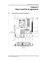
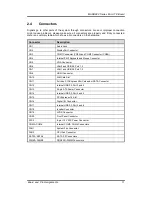
Board and Pin Assignments
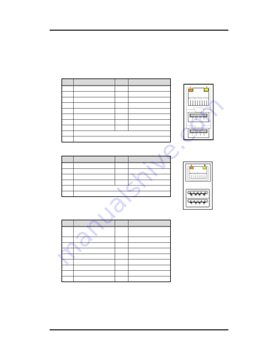
CN6
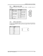
2.4.6
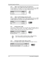
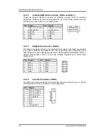
LAN and USB Connectors (CN6 and CN7)
The board comes with two high performance plug and play ethernet interfaces (RJ-45)
which are fully compliant with the IEEE 802.3 standard. Connection can be established
by plugging one end of the ethernet cable into this RJ-45 connector and the other end to
a 1000/100/10-Base-T hub.
The CN6 has lower double-deck connector for USB 2.0 port 1 and 2.
The CN7 has lower double-deck connector for USB 3.0 port 1 and 2.
CN7
Pin LAN2 Signal
Pin
USB Signal
L1
MDI0+
1
+5V standby power
L2
MDI0-
2
USB D1-
L3
MDI1+
3
USB D1+
L4
MDI1-
4
Ground (GND)
L5
MDI2+
5
+5V standby power
L6
MDI2-
6
USB D2-
L7
MDI3+
7
USB D2+
L8
MDI3-
8
Ground (GND)
A
100 LAN LED (Green)/1000 LAN LED (Orange)
B
Active LED (Yellow)
Pin LAN1 Signal
Pin
LAN1 Signal
L1
MDI0+
L5
MDI2+
L2
MDI0-
L6
MDI2-
L3
MDI1+
L7
MDI3+
L4
MDI1-
L8
MDI3-
A
100 LAN LED (Green)/1000 LAN LED (Orange)
B
Active LED (Yellow)
Pin USB Signal
Pin
USB Signal
1
USB_VCC (+5V
standby power)
10
USB_VCC (+5V
standby power)
2
USB_Data0-
11
USB_Data1-
3
US
12
US
4
GND
13
GND
5
SSRX1-
14
SSRX2-
6
SSRX1+
15
SSRX2+
7
GND
16
GND
8
SSTX1-
17
SSTX2-
9
SSTX1+
18
SSTX2+
Summary of Contents for MANO882 series
Page 6: ...vi iAMT Settings 83 iAMT Web Console 86 ...
Page 10: ...MANO882 Series Mini ITX Board 4 Introduction This page is intentionally left blank ...
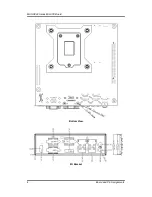
Page 12: ...MANO882 Series Mini ITX Board 6 Board and Pin Assignments Bottom View I O Bracket ...
Page 38: ...MANO882 Series Mini ITX Board 32 Hardware Installation This page is intentionally left blank ...
Page 41: ...MANO882 Series Mini ITX Board Hardware Description 35 ...
Page 43: ...MANO882 Series Mini ITX Board Hardware Description 37 ...
Page 44: ...MANO882 Series Mini ITX Board 38 Hardware Description ...
Page 46: ...MANO882 Series Mini ITX Board 40 Hardware Description This page is intentionally left blank ...
Page 74: ...MANO882 Series Mini ITX Board 68 AMI BIOS Setup Utility This page is intentionally left blank ...


