MPC103-845
User’s Manual
8
Hardware and Installation
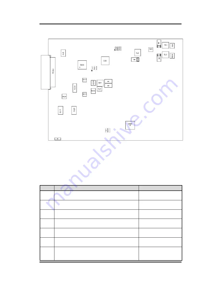
Diagram 2-2 Solder Side of the Board
2.1.1 Jumper Settings
Users can make proper jumper settings to configure the board
SBC87845
to suit the needs of
their applications.
Table 2-1 shows the default jumper settings for the MPC103-845.
Table 2-1 Default jumper settings
Jumper
Description
Default Settings
JP1
★
OSD function: LCD ON/OFF
OSD function: Touch ON/OFF
Short 1-2
Short 2-3
JP2
★
LVDS Panel Power : 3.3V
LVDS Panel Power : 5V
Short 1-2
Short 2-3
JP3
★
ATX mode
AT mode
Short 1-2
Short 2-3
JP5
Touch Controller: 4,8 WIRE
★
Touch Controller: 5 WIRE
Short 1-2
Short 2-3
JP6
★
Normal
Clear CMOS
Short 1-2
Short 2-3
JP7
★
Internal Buzzer ENABLE
Internal Buzzer DISABLE
Short 1-2
Short 2-3
JP8
★
COM1 normal mode
COM1 pin1 with power :+5V
COM1 pin9 with power :+12V
Short 3-5,4-6
Short 1-3,4-6
Short 3-5,2-4
Summary of Contents for MPC103-845
Page 6: ...vi This page is intentionally left blank ...
Page 52: ...MPC103 845 User s Manual 46 Drivers Installation This page is intentionally left blank ...
Page 56: ...MPC103 845 User s Manual 50 Watchdog Timer DIO Programming ...
Page 58: ...MPC103 845 User s Manual 52 Volume Control ...
Page 59: ...MPC103 845 User s Manual Volume Control 53 ...
Page 60: ...MPC103 845 User s Manual 54 Volume Control ...
Page 61: ...MPC103 845 User s Manual Volume Control 55 ...
Page 62: ...MPC103 845 User s Manual 56 Volume Control Step 2 System auto reboot installation completed ...
Page 65: ...MPC103 845 User s Manual Volume Control 59 Step 2 Follow the procedures and press Close ...
Page 66: ...MPC103 845 User s Manual 60 Volume Control Step 3 System auto reboot uninstallation completed ...


