

MPC152-832
User’s Manual
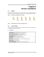
Drivers Installation
43
Step 5
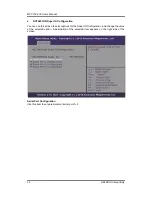
Calibration:
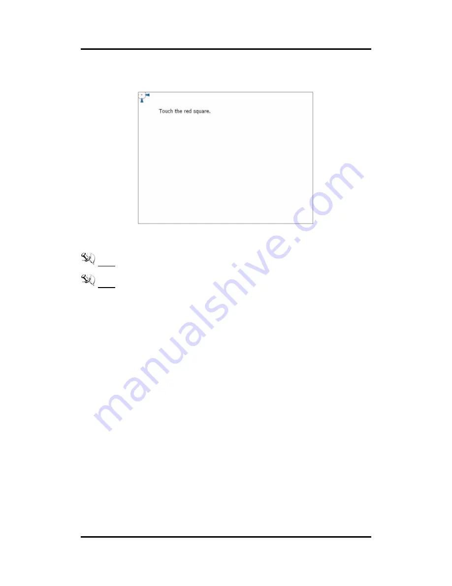
To adjust the display with touch panel, click “Calibration” and follow the calibrate
point to do calibration; there are five points on screen for calibration.
Step 6
Press OK.
NOTE: The windows may be out of rang, because the resolution requests 1024x768 or
above when using WIN 7.
NOTE: For the better system performance, please close the Windows AERO or change to
Windows Basic mode.
4.3
Embedded O.S.
The MPC152-832 provides the Windows 7 Embedded. The O.S. is supported devices which
are listed below.
WES/WES 7
Here are supported onboard devices:
Onboard Multi I/O
SATA HDD
USB
CRT/LCD display10/100/1000 base-T Ethernet
Compact Flash
Onboard Audio
Touch Screen


