background image

NA-1301 Network Appliance Server Hardware Installation Guide 


CN32/CN33 

Cl

oc

k

Da

ta

No Connect

io

n

GND

Power

1

2

5

4

3


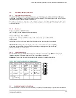
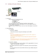
3.9      Installing USB Connector (Optional) 

The Universal Serial Bus (USB) connector on the main board is for installation of peripherals supporting 
the USB interface. CN2/CN5/CN6 is the 10-pin USB connector on the main board. 

3.10 

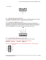
Installing ATX SB5V Power Connector   

The interface enables and supports reliable power management through improved hardware and 
operating system coordination. The specification enables new power management technology to evolve 
independently in operating systems and hardware while ensuring that they continue to work together. 

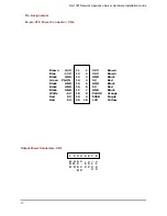
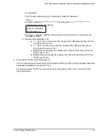
CN15 on the MAINBOARD is a 6-pin header connector that provides ATX SB5V Power. 

CN15 

1

E

X

T
S

M

I

P

W

_
P

N

P

W

_

O
N

S

B

5

V

G
N
D

2

3

4

5

6

G
N
D


3.11 

Installing ATX12V CPU Power Connector: CN35 

This connector connected to an ATX12V power supply and used for CPU Core Voltage. 

Important Note: 

Make sure your ATX12V power supply can provide as below 

+12V > 6A, 

+5V > 15A,   

-12V > 0.1A, 

+5VSB > 1A. 

The system may become unstable and may experience difficulty powering up if the power supply is 

inadequate.


AGND

USB GND

USB P0+

USB P0-

USB Power

USB P1-

USB P1+

USB GND

AGND

1

2

9

10

USB Power


Power Supply Specifications


28

Summary of Contents for NA-1301

Page 1: ...NA 1301 Hardware Installation Guide For service person only...

Page 2: ...contained in this document AXIOMTEK makes no commitment to update or to keep current the information contained in this manual AXIOMTEK reserves the right to make improvements to this document and or p...

Page 3: ...ce to radio communications However there is no guarantee that interference will not occur in a particular installation If this equipment does cause harmful interference to radio or television receptio...

Page 4: ...nents Make sure the NA 1301 Network Appliance Platform is properly grounded 3 Do not open the system s top cover If opening the cover for maintenance is a must only a trained technician is allowed to...

Page 5: ...9 3 2 2 Installing a Microprocessor CPU 21 3 3 CPU cooler installation 21 3 4 Installing a memory module DIMM 25 3 5 Installing a DMA 66 100 hard drive 25 3 6 Installing display interface 26 3 6 1 CRT...

Page 6: ...s pretty good enclosure management interface to be implemented in the factory default It can support P O S T Power on Self Test feature through hyper terminal by console port LCD module function is av...

Page 7: ...stacked up design Three gigabit LAN ports are by copper and fiber connections Support BIOS redirected to COM port feature Support RS 232 and two USB PCI 64 bit 66MHz expansion slot for another networ...

Page 8: ...ATX HRP power supplies Standard ATX power input connector Hard Drive Spacing for one IDE HDD Rear Panel Connector 3 x 10 100 1000 Base T Ethernet LAN port 1 x Console port 2 x USB port Front Panel LE...

Page 9: ...es Ultra DMA 100 supported Serial Port Two 16550 UARTs ports are with 16 byte as two RS 232 Ethernet Totally has three LAN port connections are available Three 10 100 1000 Base T Ethernet port support...

Page 10: ...NA 1301 Network Appliance Server Hardware Installation Guide This page does not contain any information Introduction 5...

Page 11: ...NA 1301 Network Appliance Server Hardware Installation Guide 1 4 Dimensions Unit mm Introduction 6...

Page 12: ...er w Gigabit LCD Module Copper w Gigabit Console port DB 9 RS 232 Console port for command initialize and diagnostic by P O S T Power on Self Test Power Lights when the NA 1281 is powered up and perfo...

Page 13: ...ppliance Server Hardware Installation Guide 1 6 Rear Panel Outlets Located at the rear panel of the NA 1301 series platform are the I O outlets You will also find the main power switch and cooling fan...

Page 14: ...on when there is an active connection on the LAN port 2 The LED flashes when there is transmit or receive activity to or from the appliance 3 The LED is dark when it off line IV Transmitted LED Dual...

Page 15: ...rver Hardware Installation Guide C h a p t e r 2 Jumpers and Connectors 2 1 System Layout The NA 1301 series was assembled by following major components They are Main Board Backplane LCD Module Power...

Page 16: ...NA 1301 Network Appliance Server Hardware Installation Guide 2 1 1 Main Board Layout Jumpers and Connectors 11...

Page 17: ...JP1 JP2 JP3 RS 232 default Short 3 5 4 6 Short 3 5 4 6 Short 1 2 RS 422 Short 1 3 2 4 Short 1 3 2 4 Short 3 4 RS 485 Short 1 3 2 4 Short 1 3 2 4 Short 5 6 7 8 2 1 2 2 CMOS Clear Jumper JP7 Options Se...

Page 18: ...pecification of the chipset and cause failure to boot up and failure in computation then it is necessary to set the JP12 and JP13 according to the following table For example when there are 3 pieces o...

Page 19: ...Port 3 4 Connector CN5 DiskOnChip Socket U22 USB Port 5 6 Connector CN2 Fan Power Connector 1 CN19 CRT Connector CN13 Fan Power Connector 2 CN31 External Mouse Connector CN33 Fan Power Connector 3 CN3...

Page 20: ...twork Appliance Server Hardware Installation Guide 2 2 1 Backplane Layout Jumpers and Connectors 2 2 1 Backplane Layout Jumpers and Connectors NA 1301 Network Appliance Server Hardware Installation Gu...

Page 21: ...U card used for Microsoft Windows Soft power ON OFF ACPI compliant CN5 Power ON OFF push button connector to front panel J1 PCI VIO PCI1 PCI2 VIO select 3 3V 5V VIO 5V short 1 3 2 4 Default 1 2 VIO 3...

Page 22: ...12V Black GND Green PS ON Black GND Black GND Black GND White 5V Red 5V Red 5V 3 3V Brown 3 3V Brown GND Black 5V Red GND Black 5V Red GND Black PW OK Orange 5VSB Purple 12V Yellow 11 1 12 2 13 3 14 4...

Page 23: ...ng this installation guide Mounting screws for disk drive and screws used in this appliance for spare Quick installation guide Hardware Installation Guide NA 1301 cable kits 1 x 40 pin IDE 1 x console...

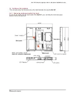
Page 24: ...ce This section provides the information about the initial installation to setup the NA 1301 3 2 1 Removing and Replacing the Top Cover To gain access into the internal components of the NA 1301 you m...

Page 25: ...NA 1301 Network Appliance Server Hardware Installation Guide Hardware Description 20...

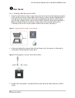
Page 26: ...mpletely into the socket turn the actuator until the processor drops completely in Note You should not have to press down on the processor If the processor does not drop completely into the socket tur...

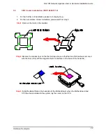
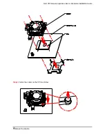
Page 27: ...the liner on the insulator Adhesiv StamarK minati TM Laminating 3M Stama StamarK TM La Step2 Remove the release liner on the thermal tape Be sure that the blue film has been removed with the liner On...

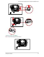
Page 28: ...NA 1301 Network Appliance Server Hardware Installation Guide Step4 Fasten the cooler on the CPU as follow Hardware Description 23...

Page 29: ...NA 1301 Network Appliance Server Hardware Installation Guide THE CLIP IS WELL FASTENING Step5 Connect the housing to the Power Socket Hardware Description 24...

Page 30: ...ary to match DIMM timings A CL 2 0 DIMM can be paired with a CL 2 5 DIMM as long as the geometry matches Attention When you handle electrostatic discharge sensitive ESDs take precautions to avoid dama...

Page 31: ...olor and Monochrome Dual Drive and Single Drive panels SMARTMAP intelligent color to gray scale conversion enhances text legibility Integrated programmable linear address feature accelerates GUI perfo...

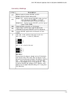
Page 32: ...are selected via IRQ4 and IRQ3 respectively Additionally both ports can be enabled or disabled via BIOS setting RS 232 422 485 PIN Assignment CN8 CN7 Description CN8 CN7 D SU B RS 232 RS 422 RS 485 1...

Page 33: ...management technology to evolve independently in operating systems and hardware while ensuring that they continue to work together CN15 on the MAINBOARD is a 6 pin header connector that provides ATX S...

Page 34: ...try point on left upper corner of LCM Attention It is just move the RAM flag to point out into the entry point of LCM It needs to be progress this commands about 40 s If we need to clear the contents...

Page 35: ...ex to PC It is ASCII code for U b Down when it was press then release the LCM will send 44hex to PC it is ASCII code for D c ESC when it was press then release the LCM will send 4Chex to PC it is ASCI...

Page 36: ...NA 1301 Network Appliance Server Hardware Installation Guide Power Supply Specifications 31...

Page 37: ...rt the system by pressing the Reset button or simultaneously pressing the Ctrl Alt and Delete keys You can also restart by turning the system OFF and back ON again The following message will appear on...

Page 38: ...F1 General Help F5 Previous Values F6 Fail Safe Defaults F7 Optimized Defaults At the bottom of the menu are the control keys for use on this menu If you need any help in each item field you can pres...

Page 39: ...ler of HDD interface is SCSI select None If the controller of HDD interface is CD ROM select None CYLS number of cylinders LANDZONE landing zone HEADS number of heads SECTORS number of sectors PRECOMP...

Page 40: ...Small Logo EPA Show Disabled Move Enter Select PU PD Value F10 Save ESC Exit F1 General Help Virus Warning This item protects the boot sector and partition table of your hard disk against accidental...

Page 41: ...d typematic delay programming Disabled Disable typematic rate and typematic delay programming The system BIOS will use default value of these 2 items and the default is controlled by keyboard Typemati...

Page 42: ...select OS 2 otherwise under non OS2 default is NON OS2 The default value is Non OS2 Console Redirection This item allows you to enable or disable the BIOS boot up and redirect to console port feature...

Page 43: ...ss Enter setting DRAM timming as below Phoenix AwardBIOS CMOS Setup Utility Advanced Chipset Features DRAM Timing Selectable By SPD Item Help CAS Latency Time 2 Active to Precharge Delay 5 Menu Level...

Page 44: ...rmance However if any program writes to this memory area a system error may result The Choice Enabled Disabled Video RAM Cacheable Select Enabled allows caching of the A B segment resulting in better...

Page 45: ...ary Secondary PCI IDE The integrated peripheral controller contains an IDE interface with support for two IDE channels Select Enabled to activate each channel separately The choice Enabled Disabled ID...

Page 46: ...tion the KB POWER ON Password line appears Press Enter and you ll be prompted to enter and confirm a password of your choice After setting the password succeeding attempts to power ON the system will...

Page 47: ...1 Disabled COM Port Disabled PCI PIRQ A D Disabled Move Enter Select PU PD Value F10 Save ESC Exit F1 General Help F5 Previous Values F6 Fail Safe Defaults F7 Optimized Defaults ACPI Function This it...

Page 48: ...U THRM Throttling Select the CPU THRM Throttling rate The choice 12 5 25 0 37 5 50 0 62 5 75 0 87 5 Power On by Ring An input signal on the serial Ring Indicator RI line in other words an incoming cal...

Page 49: ...e ESC Exit F1 General Help F5 Previous Values F6 Fail Safe Defaults F7 Optimized Defaults PNP OS Installed This item allows you to determine install PnP OS or not The options available are Yes and No...

Page 50: ...urrent FAN2 Speed Vcore Vcc3 5V 12V 12V 5V Move Enter Select PU PD Value F10 Save ESC Exit F1 General Help F5 Previous Values F6 Fail Safe Defaults F7 Optimized Defaults Current System Temp Show you t...

Page 51: ...led it will send the clock signal to all DIMM and PCI socket The choice Enabled Disabled Spread Spectrum Modulated This item allows you to enable disable the spread spectrum modulate The choice Enable...

Page 52: ...ABLED When a password is enabled you have to type it every time you enter Setup This prevents any unauthorized person from changing your system configuration Additionally when a password is enabled yo...

Page 53: ...tions Typing N will return you to Setup utility Phoenix AwardBIOS CMOS Setup Utility Standard CMOS Features Frequency Voltage Control Advanced BIOS Features Load Fail Safe Defaults Advanced Chipset Fe...

Page 54: ...12V dc 1 8A maximum Minimum clearance from uninsulated live parts 4 0 mm The equipment is to be installed in an environment with maximum ambient temperature must not exceed 40 C The openings on the en...

Page 55: ...NA 1301 Network Appliance Server Hardware Installation Guide This page does not contain any information Warning 50...

Reviews: