background image


NA860 


Network Appliance 

 
User’s Manual


Summary of Contents for NA860 series

Page 1: ...NA860 Network Appliance User s Manual...

Page 2: ...nual Axiomtek reserves the right to change or revise this document and or product at any time without notice No part of this document may be reproduced stored in a retrieval system or transmitted in a...

Page 3: ...However there is no guarantee that interference will not occur in a particular installation If this equipment does cause harmful interference to radio or television reception which can be determined b...

Page 4: ...d technician is allowed to do so Integrated circuits on computer boards are sensitive to static electricity To avoid damaging chips from electrostatic discharge observe the following precautions Befor...

Page 5: ...ection JP1 15 2 5 Connectors 16 2 5 1 FAN Connector FAN1 FAN6 17 2 5 2 ATX 12V CPU Power Connector CN1 CN2 17 2 5 3 Front Panel Bezel Connector CN6 17 2 5 4 ATX Power Connector CN7 18 2 5 5 LAN Connec...

Page 6: ...Starting 33 3 2 Navigation Keys 33 3 3 Main Menu 35 3 4 Advanced Menu 36 3 5 Platform Configuration 53 3 6 Socket Configuration 58 3 7 Security Menu 60 3 8 Boot Menu 61 3 9 Save Exit Menu 63 Appendix...

Page 7: ...ring event log data the NA860 utilizes two 2 5 SATA HDD For greater flexibility and easier maintenance the NA860 has eight front accessible expansion slots that allow developers to configure different...

Page 8: ...256Mbit PnP Flash BIOS with function of BIOS redirected to COM port HDD Tray Two 2 5 Trays for SATA HDD support hot swappable LAN The default is two 10 100 1000Mbps LAN ports Intel i210AT Expandable u...

Page 9: ...Note NA860 can support total 8 slots of LAN module but for LAN Bypass feature can be supported 5 slots only Hardware Monitoring Controller Nuvoton NCT6102D NCT7802Y CPU temperature system temperature...

Page 10: ...es User s Manual 4 Introduction Chassis Material Steel Dimensions 88mm 3 46 H x 430mm 16 92 W x 562mm D Certificate FCC class A CE class A Note All specifications and images are subject to change with...

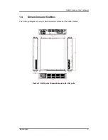
Page 11: ...NA860 Series User s Manual Introduction 5 1 4 Dimensions and Outlines The following diagram shows you dimensions and outlines of the NA860 Series Default 2 LAN ports Expandable up to 66 LAN ports...

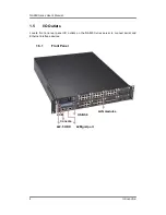
Page 12: ...nual 6 Introduction 1 5 I O Outlets Locate front and rear panel I O outlets on the NA860 Series server to connect serial and Ethernet interface devices 1 5 1 Front Panel LAN modules LCM Console USB3 0...

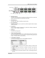
Page 13: ...iagnostic support by P O S T Power On Self Test USB Ports Two USB 3 0 ports supported Reset Tact Switch default It is for reset the system to reboot your computer instead of turning OFF the power swit...

Page 14: ...D for LAN Port The orange LED is on when the LAN port connection is working The LED flashes when transmitting or receiving any signals to or from the appliance The LED is dark when the appliance is of...

Page 15: ...let AC and also provide an alarm reset for power supply when one of power has damage Power Alarm Reset Alarm reset is used to clear fail status by shorting circuit activities Buzzer should alarm if si...

Page 16: ...NA860 Series User s Manual 10 Introduction This page is intentionally left blank...

Page 17: ...The NA860 Series network appliance hardware platform Power cord x2 redundant power 1 1 Mounting brackets for rack installation left right x 2 Screw for mounting bracket x4 Plastic stand for stack up...

Page 18: ...NA860 Series User s Manual 12 Hardware and Installation 2 2 Board Layout TOP...

Page 19: ...NA860 Series User s Manual Hardware and Installation 13 BOTTOM...

Page 20: ...erly configure jumper settings on the main board in this appliance to meet your application purpose Below we list a summary table of all jumpers and default settings for onboard devices Jumper Definit...

Page 21: ...section provides the information about jumpers and connectors of NA570 Series Properly configure jumper settings on the main board in this appliance to meet your application purpose Below we list a su...

Page 22: ...Connector CN6 ATX Power Connector CN7 LAN Connector optional for IPMI Management port CN9 Mini PCIe Card Connector Full CN11 LAN Connector for I210 port CN12 CN20 General Purpose Input Output Connecto...

Page 23: ...is 3 pin connector Pin 1 3 5 connects a LED indicator to the system power switch on the case Pin 1 is assigned as and Pin 3 Pin 5 as The Power LED lights up when the system is powered ON External Spea...

Page 24: ...pply HDD Activity LED This connection is linked to hard drive activity LED on the control panel LED flashes when HDD is being accessed The 2 pin connector Pin 13 14 connects the hard disk drive to the...

Page 25: ...he IPMI Management port pin assignments are listed on the following table Pin Signal 1 1000M speed signal 2 100M speed signal 3 Ground GND 4 MDI3 5 MDI3 6 MDI2 7 MDI2 8 MDI1 9 MDI1 10 MDI0 11 MDI0 12...

Page 26: ...use 11 REFCLK 12 No use 13 REFCLK 14 No use 15 Ground GND 16 No use 17 No use 18 Ground GND 19 No use 20 W_DISABLE 21 Ground GND 22 PERST 23 PE_RXN3 24 3 3VSB 25 PE_RXP3 26 Ground GND 27 Ground GND 2...

Page 27: ...The I210 Management port pin assignments are listed on the following table Pin Signal 1 1000M speed signal 2 100M speed signal 3 Ground GND 4 MDI3 5 MDI3 6 MDI2 7 MDI2 8 MDI1 9 MDI1 10 MDI0 11 MDI0 12...

Page 28: ...gnals 2 5 9 I O board connector CN15 The I O board connector assignments are listed on the following table Pin Signal 9 2 10 1 CN14 1 Ground GND 2 Ground GND 3 SIO_GPIO7 4 SIO_GPIO3 5 SIO_GPIO6 6 SIO_...

Page 29: ...The I210 Management port pin assignments are listed on the following table Pin Signal 1 1000M speed signal 2 100M speed signal 3 Ground GND 4 MDI3 5 MDI3 6 MDI2 7 MDI2 8 MDI1 9 MDI1 10 MDI0 11 MDI0 12...

Page 30: ...a 15 pin D Sub connector for the CRT VGA display Pin Signal VGA1 1 VGA_R 2 CRT_DETECT 3 VGA_G 4 NC 5 VGA_B 6 GND 7 VCC 5V 8 VGADDCDATA 9 GND 10 GND 11 GND 12 DAC_L_HSYNC 13 GND 14 DAC_L_VSYNC 15 VGADD...

Page 31: ...10 pin standard Universal Serial Bus USB connector on this board is for installing versatile USB interface peripherals Pin Signal Pin Signal USB1 USB2 1 USB_POWER 2 USB_POWER 3 USB_PN1 4 USB_PN2 5 US...

Page 32: ...erial ATA hard disk drives Each SATA connector supports a single SATA device Pin Signal Pin Signal SATA1 SATA4 1 GND 2 TX 3 TX 4 GND 5 RX 6 RX 7 GND 2 5 17 ATX 4 Pin 12V In Connector ATX1 You can conn...

Page 33: ...eon processors html The LGA3647 processor socket comes with a cover to protect the processor Please install the processor into the CPU socket step by step as below Remove the socket protective cover P...

Page 34: ...NA860 Series User s Manual 28 Hardware and Installation Open this lever first And then open this lever 1 2...

Page 35: ...NA860 Series User s Manual Hardware and Installation 29 Note To protect the CPU socket pins do not remove the CPU cap when the CPU is not installed...

Page 36: ...nstall the memory modules 1 Push down latches on each side of the DIMM socket 2 Align the memory module with the socket that notches of memory module must match the socket keys for a correct installat...

Page 37: ...60 Series User s Manual Hardware and Installation 31 2 6 3 Install the Expansion Slot optional When install the riser card should remove the air dock s screws CPU1 then using sticker to firm the air d...

Page 38: ...NA860 Series User s Manual 32 Hardware and Installation This page is intentionally left blank...

Page 39: ...d press the DEL or ESC key immediately After you press the DEL or ESC key the main BIOS setup menu displays You can access the other setup screens from the main BIOS setup menu such as the Advanced an...

Page 40: ...1 The F1 key allows you to display the general help screen F2 The F2 key allows you to load previous values F3 The F3 key allows you to load optimized defaults F4 The F4 key allows you to save any cha...

Page 41: ...be set up as described below The Main BIOS setup screen is shown below System Language Use this item to choose the BIOS language System Date Time Use this option to change the system time and date Hi...

Page 42: ...ct any of the items in the left frame of the screen to go to the sub menus Trusted Computing AST2500SEC Super IO Configuration NCT6102D Super IO Configuration HW Monitor Serial Port Console Redirectio...

Page 43: ...NA860 Series User s Manual AMI BIOS Setup Utility 37 Security Device Support This item allows you to select the security device support Configuration options Enabled or Disabled...

Page 44: ...NA860 Series User s Manual 38 AMI BIOS Setup Utility...

Page 45: ...ect options for the Super IO Configuration and change the value of the selected option A description of the selected item appears on the right side of the screen Serial Port 1 Configuration This optio...

Page 46: ...y Serial Port 2 Configuration This option specifies the base I O port address and Interrupt Request address of serial port 2 The Optimal setting is 248h IRQ10 NCT6102 Super IO Configuration This scree...

Page 47: ...NA860 Series User s Manual AMI BIOS Setup Utility 41...

Page 48: ...NA860 Series User s Manual 42 AMI BIOS Setup Utility...

Page 49: ...NA860 Series User s Manual AMI BIOS Setup Utility 43 HW Monitor This screen monitors hardware health status...

Page 50: ...NA860 Series User s Manual 44 AMI BIOS Setup Utility This screen displays the fan speed in RPM...

Page 51: ...NA860 Series User s Manual AMI BIOS Setup Utility 45 Serial Port Console Redirection...

Page 52: ...tility Console Redirection Use this item to enable or disable console redirection The settings specify how the host computer and remote computer which the user is using will exchange data Both compute...

Page 53: ...rminals Recorder Mode This item allows you to select the recorder mode The configuration options Enabled and Disabled Resolution 100x31 This item allows you to select the data bits The configuration o...

Page 54: ...NA860 Series User s Manual 48 AMI BIOS Setup Utility CSM Configuration This screen shows the CSM Configuration and you can enable disable option ROM execution settings...

Page 55: ...NA860 Series User s Manual AMI BIOS Setup Utility 49 LBP PowerOn All SEG For Power On LAN Bypass setting use LBP PowerOn item to Disabled Enabled or Last State for LAN Bypass all segments...

Page 56: ...p Utility LBP Power Off All SEG For Power off LAN Bypass setting use LBP PowerOff item to Disabled Enabled or Last State for LAN Bypass all segments PCIe LAN IO Resourece For LAN IO Resource setting u...

Page 57: ...NA860 Series User s Manual AMI BIOS Setup Utility 51 Network Storage For Network setting use Network item to Do not launch or UEFI or legacy mode...

Page 58: ...SB Support Due to the limited space of the BIOS ROM the support for legacy USB keyboard in DOS mode is by default set to Disabled With more BIOS ROM space available it will be able to support more adv...

Page 59: ...nfiguration The Chipset menu allows users to change the advanced chipset settings You can select any of the items in the left frame of the screen to go to the sub menus PCH Configuration Server ME Con...

Page 60: ...Utility PCH Configuration You can select any of the items in the screen PCH SATA Configuration USB Configuration PCH SATA Configuration SATA Controller This item allows you to select the SATA controll...

Page 61: ...gure SATA Configuration options AHCI RAID mode AHCI mode allows the onboard storage driver to enable advanced SATA features that increases storage performance or workloads where multiple simultaneous...

Page 62: ...you to select the configure SATA Configuration options AHCI and RAID AHCI mode allows the onboard storage driver to enable advanced SATA features that increases storage performance or workloads where...

Page 63: ...NA860 Series User s Manual AMI BIOS Setup Utility 57 Server ME Configuration...

Page 64: ...he Chipset menu allows users to change the advanced chipset settings You can select any of the items in the left frame of the screen to go to the sub menus Processor Configuration IIO Configuration Fo...

Page 65: ...NA860 Series User s Manual AMI BIOS Setup Utility 59 IIO Configuration...

Page 66: ...rity Menu The Security menu allows users to change the security settings for the system Administrator Password This item indicates whether an administrator password has been set If the password has be...

Page 67: ...lity 61 3 8 Boot Menu The Boot menu allows users to change boot options of the system You can select any of the items in the left frame of the screen to go to the sub menus Setup Prompt Timeout Number...

Page 68: ...Series User s Manual 62 AMI BIOS Setup Utility Boot Option Priorities You could set the system boot order of the legacy devices in this group You could set the system boot order in option 1 UEFI or Di...

Page 69: ...d your system configuration with optimal or fail safe default values Save Changes and Exit When you have completed the system configuration changes select this option to leave Setup and return to Main...

Page 70: ...the system configuration and return to Main Menu Select Discard Changes and Exit from the Save Exit menu and press Enter Select Yes to discard changes and exit Save Changes When you have completed the...

Page 71: ...s to discard changes Restore Defaults It automatically sets all Setup options to a complete set of default settings when you select this option The Optimal settings are designed for maximum system per...

Page 72: ...nfiguration changes done so far as User Defaults Select Save as User Defaults from the Save Exit menu and press Enter Restore User Defaults It automatically sets all Setup options to a complete set of...

Page 73: ...ram to control bypass operation behavior to fit your requirement Note If you need sample codes please contact our FAE directly And they are for reference purposes only Mother Board Slot 1 Lan Module S...

Page 74: ...setting of LAN bypass Timer Control register Bit 5 4 Not used Bits 3 0 SEGN4 1 Select each segment by setting the corresponding bit to 1 When the bit is set to 0 no action happens upon the segment Dat...

Page 75: ...FE 7 6 5 4 3 2 1 0 TEXP X X X X TVAL2 TVAL1 TVAL0 R W W W Default value 00000000 Bit 7 TEXP Read Only This bit indicates status of hardware timer 0 Timer has not expired 1 Timer has expired Bits 6 3 N...

Page 76: ...ister Address Slot 1 Slot 2 Slot 3 Slot 4 Slot 5 Slot 6 Slot 7 Slot 8 0x8E3 0x8E7 0x8EB 0x8EF 0x8F3 0x8F7 0x8FB 0x8FF 7 6 5 4 3 2 1 0 VER3 VER2 VER1 VER0 BY4 BY3 BY2 BY1 R R R R R R R R Bit3 0 Lan Byp...

Page 77: ...mer for System Reset WDT Watchdog Timer The hardware supports the WDT Watchdog Timer function While time out happens after a defaulted period the WDT will reset the system Note If you need sample code...

Page 78: ...NA860 Series User s Manual 72 WDT Timer For System Reset This page is intentionally left blank...
Page 79: ...ions for your selection Limitation Single CPU only supports 4 LAN modules Slot 1 4 Note NA860 can support total 8 slots of LAN module but for LAN Bypass feature can be supported 5 slots only Use this...

Page 80: ...is on when the LAN port connection is working The LED flashes when transmitting or receiving any signals to or from the appliance The LED is dark when the appliance is off Link LED for LAN port 1 por...

Page 81: ...The LED is dark when the appliance is off Link LED for LAN port 1 port 2 port 3 port 4 The double color LED light indicates 10 100 1000Mbps transfer rate When the orange color LED light is radiating...

Page 82: ...NA860 Series User s Manual 76 LAN Module Expansion AX93336 4FI Transfer Rate LED Light Color Fiber port Active Orange Fiber port Link Orange...

Page 83: ...860 Series User s Manual LAN Module Expansion 77 AX93322 8FI Transfer Rate LED Light Color Down Fiber port Active Orange Up Fiber port Active Orange Down Fiber port Link Orange Up Fiber port Link Oran...

Page 84: ...t 3 port 4 The orange LED is on when the LAN port connection is working The LED flashes when transmitting or receiving any signals to or from the appliance The LED is dark when the appliance is off Li...

Page 85: ...s on when the LAN port connection is working The LED flashes when transmitting or receiving any signals to or from the appliance The LED is dark when the appliance is off Link LED for LAN port 1 port...

Page 86: ...or receiving any signals to or from the appliance The LED is dark when the appliance is off Link LED for LAN port 1 port 2 The double color LED light indicates 1000 10000Mbps transfer rate When the o...

Page 87: ...A maximum Minimum clearance from uninsulated live parts 4 0 mm The equipment is to be installed in an environment with maximum ambient temperature must not exceed 40 C The openings on the enclosure ar...

Page 88: ...NA860 Series User s Manual 82 warning This page is intentionally left blank...
Reviews: