NA860 Series User
’s Manual
Hardware and Installation
19
2.5.5
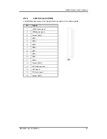
LAN Connector(CN9)
The IPMI Management port pin assignments are listed on the following table.
Pin
Signal
1
1000M speed signal
2
100M speed signal
3
Ground (GND)
4
MDI3-
5
MDI3+
6
MDI2-
7
MDI2+
8
MDI1-
9
MDI1+
10
MDI0-
11
MDI0+
12
Ground (GND)
13
3.3V standby power
14
LINK signal
15
3.3V main power
16
Ground (GND)
Summary of Contents for NA860 series
Page 1: ...NA860 Network Appliance User s Manual...
Page 16: ...NA860 Series User s Manual 10 Introduction This page is intentionally left blank...
Page 18: ...NA860 Series User s Manual 12 Hardware and Installation 2 2 Board Layout TOP...
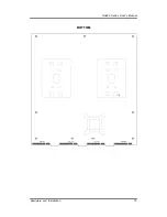
Page 19: ...NA860 Series User s Manual Hardware and Installation 13 BOTTOM...
Page 38: ...NA860 Series User s Manual 32 Hardware and Installation This page is intentionally left blank...
Page 44: ...NA860 Series User s Manual 38 AMI BIOS Setup Utility...
Page 47: ...NA860 Series User s Manual AMI BIOS Setup Utility 41...
Page 48: ...NA860 Series User s Manual 42 AMI BIOS Setup Utility...
Page 50: ...NA860 Series User s Manual 44 AMI BIOS Setup Utility This screen displays the fan speed in RPM...
Page 51: ...NA860 Series User s Manual AMI BIOS Setup Utility 45 Serial Port Console Redirection...
Page 63: ...NA860 Series User s Manual AMI BIOS Setup Utility 57 Server ME Configuration...
Page 65: ...NA860 Series User s Manual AMI BIOS Setup Utility 59 IIO Configuration...
Page 78: ...NA860 Series User s Manual 72 WDT Timer For System Reset This page is intentionally left blank...
Page 88: ...NA860 Series User s Manual 82 warning This page is intentionally left blank...

