background image

SBC81203 LGA775 SBC User’s Manual 


Award BIOS Utility


46 

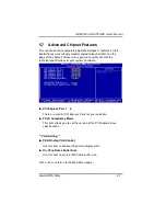
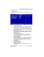
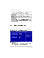
** PCI Express relative items ** 


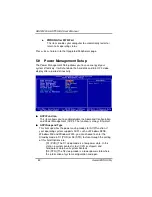
Maximum Payload Size 

When using DDR SDRAM and Buffer size selection, another 
consideration in designing a payload memory is the size of the 
buffer for data storage. Maximum Payload Size defines the 
maximum TLP (Transaction Layer Packet) data payload size for 
the device.  

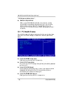
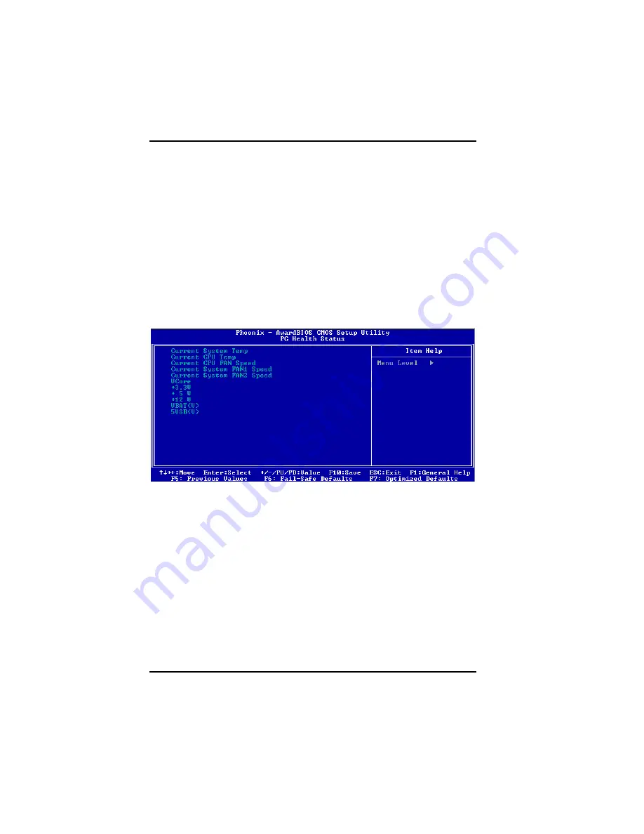
5.11  PC Health Status 

This section supports hardware monitering that lets you monitor those 
parameters for critical voltages, temperatures and fan speed of the 
board. 


Current SYSTEM Temperature 

Show you the current system1 temperature. 


Current CPU Temperature 

The current system CPU temperature will be automatically detected 
by the system. 


Current CPU FAN Speed 

These optional and read-only items show current speeds in RPM 
(Revolution Per Minute) for the CPU fan and chassis fan as 
monitored by the hardware monitoring IC.  


Current SYSTEM FAN1 Speed 

Show you the current system fan1 temperature. 
 

Summary of Contents for SBC81203 Series

Page 1: ...SBC81203 Series Intel CoreTM Duo Pentium D Pentium 4 Celeron D PICMG 1 0 Single Board Computer User s Manual...

Page 2: ...manual AXIOMTEK reserves the right to change or revise this document and or product at any time without notice No part of this document may be reproduced stored in a retrieval system or transmitted in...

Page 3: ...arges static electricity from your body Wear a wrist grounding strap available from most electronic component stores when handling boards and components Trademarks Acknowledgments AXIOMTEK is a tradem...

Page 4: ...ors 12 2 4 4 ATX 4 Pin 12V In Connector 12 2 4 5 Floppy Disk Port Connector 13 2 4 6 Parallel IDE Interface Connector 14 2 4 7 SATA Connectors 15 2 4 8 USB Connectors 15 2 4 9 Front Panel Connector 16...

Page 5: ...Voltage Control 48 5 13 Load Optimized Defaults 49 5 14 Set Supervisor User Password 50 5 15 Save Exit Setup 51 5 16 Exit Without Saving 52 Chapter 6 Installation of Drivers 53 6 1 Installing Chipset...

Page 6: ...vi MEMO...

Page 7: ...h high bandwidth interfaces multiple I O functions for interactive applications and various embedded computing solutions There are two DDR2 DIMM sockets for dual channel DDR2 533 667 maximum memory ca...

Page 8: ...egrated in CPU IDE Interface One IDE connector and up to two IDE devices Ultra DMA ATA33 66 100 supported Onboard Multi I O Parallel Port one bi directional with ECP EPP SPP support Serial Port one fo...

Page 9: ...rd Hardware Monitoring Controller Winbond W83627HF AW detection of CPU temperature system temperature power failure and fan speed Watchdog Timer Software programmable time interval and hardware reset...

Page 10: ...SBC81203 LGA775 SBC User s Manual Introduction 4 1 3 Block Diagram 1 4 I O Bracket...

Page 11: ...SBC81203 LGA775 SBC User s Manual Jumpers and Connectors 5 C h a p t e r 2 Jumpers and Connectors 2 1 Board Dimensions...

Page 12: ...SBC81203 LGA775 SBC User s Manual Jumpers and Connectors 6 2 2 Board Layout...

Page 13: ...2 3 1 COM2 Mode Select Jumpers JP4 JP5 JP6 These jumpers select the COM2 port s communication mode to operate RS 232 or RS 422 485 Description Function Jumper Setting RS 232 Default JP4 1 3 5 7 2 4 6...

Page 14: ...nual Jumpers and Connectors 8 2 3 2 CMOS Clear Jumper JP15 You may need to use this jumper is to clear the CMOS memory if incorrect BIOS settings Description Function Jumper Setting Normal Default JP1...

Page 15: ...nnectors Label Connectors Label Audio Output CN1 USB 1 USB1 2 Parallel Port PRN1 USB 3 4 USB5 6 COM1 Port COM1 USB 2 USB3 4 ATX 4 Pin 12V In CN2 Front Panel CN5 CD AUX In AUX1 System FAN1 FAN2 COM2 Po...

Page 16: ...xtended capabilities port ECP is IEEE 1284 compliant Pin Signal Pin Signal 1 Strobe 2 Data 0 3 Data 1 4 Data 2 5 Data 3 6 Data 4 7 Data 5 8 Data 6 9 Data 7 10 Acknowledge 11 Busy 12 Paper Empty 13 Pri...

Page 17: ...ata Set Ready DSR 3 Receive Data RXD 4 Request to Send RTS 5 Transmit Data TXD 6 Clear to Send CTS 7 Data Terminal Ready DTR 8 Ring Indicator RI 9 Ground GND 10 NC COM1 COM2 2 2 2 2 4 4 4 4 6 6 6 6 1...

Page 18: ...ne of the following types 5 25 360KB 1 2MB and 3 5 720KB 1 44MB 2 88MB Pin Signal Pin Signal Pin Signal 1 GND 2 Reduce write current 3 GND 4 N C 5 GND 6 N C 7 GND 8 Index 9 GND 10 Motor enable A 11 GN...

Page 19: ...n Description Pin Description 1 Reset 2 GND 3 Data 7 4 Data 8 5 Data 6 6 Data 9 7 Data 5 8 Data 10 9 Data 4 10 Data 11 11 Data 3 12 Data 12 13 Data 2 14 Data 13 15 Data 1 16 Data 14 17 Data 0 18 Data...

Page 20: ...on this board are for installing versatile USB interface peripherals These are 10 pin standard USB connectors Pin Signal Pin Signal 1 USB POWER 2 USB POWER 3 USB P0 4 USB P1 5 USB P0 6 USB P1 7 USB GN...

Page 21: ...2 4 6 8 can be connected to the case mounted speaker unit or internal buzzer Hardware Reset Pins 11 and 12 are designed for Hardware Reset HDD Activity LED This connector extends to the hard drive ac...

Page 22: ...ower supply Pin Signal Pin Signal 1 EXTSMI 2 GND 3 POWER BUTTOM 4 GND 5 SUSB 6 5VSB CN4 6 5 4 3 2 1 2 4 11 Internal Mouse Keyboard Connector MS1 KB1 The board provides a keyboard KB1 and Mouse MS1 int...

Page 23: ...SBC81203 LGA775 SBC User s Manual Jumpers and Connectors 17 MEMO...

Page 24: ...e access Intel website for more detailed information http www intel com 3 1 Installing the Processor The LGA775 processor socket comes with a cover to protect the processor Please install the processo...

Page 25: ...SBC81203 LGA775 SBC User s Manual Hardware Installation 19 Remove the plastic cap E from the cover Open the cover C you can see the contact Be careful not to touch the contact D...

Page 26: ...s Manual Hardware Installation 20 Place the CPU down into the socket Be careful not to touch the contact Hold the edges of the CPU and orientate it as the marked direction G down into the socket to ma...

Page 27: ...SBC81203 LGA775 SBC User s Manual Hardware Installation 21 Slightly push down the cover and hook the lever I J The CPU is completely locked Orientate the CPU cooling fan to fixing holes on the board...

Page 28: ...SBC81203 LGA775 SBC User s Manual Hardware Installation 22 Screw the CPU cooling fan onto the board Make sure the CPU fan is plugged to the CPU fan connector...

Page 29: ...stall the memory modules 1 Push down latches on each side of the DIMM socket 2 Align the memory module with the socket that notches of memory module must match the socket keys for a correct intallatio...

Page 30: ...x environments The system performance depends on the microprocessor Make sure your installed microprocessor with all correct settings that prevents the CPU from damages 4 2 BIOS The SBC81203 Series us...

Page 31: ...rd controller 070 07F Real time clock NMI 080 09F DMA page register 0A0 0BF Interrupt controller 2 0F0 Clear math coprocessor busy signal 0C0 0DF DMA controller 2 0F1 Reset math coprocessor 0F8 0FF Ma...

Page 32: ...y or press the Del and or Ctrl Alt and Esc keys simultaneously when the following message appears at the bottom of the screen during POST Power on Self Test TO ENTER SETUP PRESS DEL KEY If the message...

Page 33: ...ange color from total 16 colors F2 to select color forward Shift F2 to select color backward F3 key Reserved F4 key Reserved F5 key Restore the previous CMOS value from CMOS only for Option Page Setup...

Page 34: ...the Setup Page you intend to configure then press Enter to accept or enter its sub menu NOTE If your computer can not boot after making and saving system changes with Setup the Award BIOS will reset...

Page 35: ...Date The date format is day date month year Press F3 to show the calendar day It is determined by the BIOS and read only from Sunday to Saturday date It can be keyed with the numerical function key fr...

Page 36: ...ly key in the information and press Enter This information should be provided in the documentation from your hard disk vendor or the system manufacturer If the HDD interface controller supports ESDI s...

Page 37: ...rors Whenever BIOS detects a non fatal error the system will stop and you will be prompted All But Keyboard The system booting will not stop for a keyboard error it will stop for other errors All But...

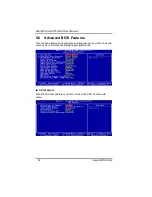
Page 38: ...OS Utility 32 5 6 Advanced BIOS Features This section allows you to configure and improve your system to set up some system features according to your preference CPU Feature Scroll to this item and pr...

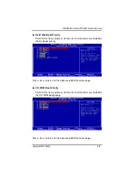
Page 39: ...tem and press Enter to view the sub menu to decide the disk boot priority Press Esc to return to the Advanced BIOS Features page CD ROM Boot Priority Scroll to this item and press Enter to view the su...

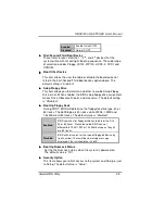
Page 40: ...essage will appear for attempts to access the boot sector or hard disk partition table NOTE This function is only available with DOS and other operating systems that do not trap INT13 CPU L1 L2 Cache...

Page 41: ...ignment makes Drive A become Drive B and vice versa The default setting is Disabled Boot Up Floppy Seek During POST BIOS will determine the floppy disk drive type 40 or 80 tracks The 360Kb type is 40...

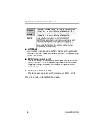
Page 42: ...ter and it will disable the security Once the security is disabled the system will boot and you can enter Setup freely APIC Mode Use this item to enable or disable APIC Advanced Programmable Interrupt...

Page 43: ...you are very familiar with the technical specifications of your system hardware PCI Express Port 1 6 There are several PCI Express Ports for your selection PCI E Compliancy Mode This item allows you...

Page 44: ...hip IDE Device Scroll to this item and press Enter to view the sub menu OnChip IDE Device IDE HDD Block Mode Block mode is also called block transfer multiple commands or multiple sector read write If...

Page 45: ...for each of the four IDE devices that the onboard IDE interface supports Modes 0 to 4 provide successively increased performance In Auto mode the system automatically determines the best mode for each...

Page 46: ...l to this item and press Enter to view the sub menu Onboard Device USB Controller Enable this item if you are using the USB in the system You should disable this item if a higher level controller is a...

Page 47: ...ort 1 2 Select an address and corresponding interrupt for the serial port Options 3F8 IRQ4 2E8 IRQ3 3E8 IRQ4 2F8 IRQ3 Disabled Auto Onboard Paralellel Port This item allows you to determine the I O ad...

Page 48: ...allows you to enable disable the Advanced Configuration and Power Management ACPI The function is always Enabled ACPI Suspend Type This item specifies the power saving modes for ACPI function If your...

Page 49: ...A Use the supplied software for your video subsystem to select video power management values Blank Screen The System only writes blanks to the video buffer Video Off In Suspend This item defines if th...

Page 50: ...OFF through the power switch this option will delay the complete system power OFF sequence approximately 4 seconds Within this delay period the system will temporarily enter into the Suspend Mode enab...

Page 51: ...OS automatically assigns them The default value is Manual IRQ Resources When resources are controlled manually assign each system interrupt to one of the following types in accordance with the type of...

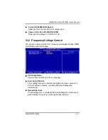
Page 52: ...s This section supports hardware monitering that lets you monitor those parameters for critical voltages temperatures and fan speed of the board Current SYSTEM Temperature Show you the current system1...

Page 53: ...on is to control the CPU frequency and Supply Voltage DIMM OverVoltage and AGP voltage CPU Clock Ratio Use this item to select the CPU s frequency Auto Detect PCI Clk The enabled item can automaticall...

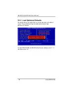
Page 54: ...13 Load Optimized Defaults This option allows you to load your system configuration with default values These default settings are optimized to enable high performance features To load CMOS SRAM with...

Page 55: ...may also press Esc to abort this selection and not enter a password To disable the password just press Enter when you are prompted to enter a password A message will confirm the password is getting d...

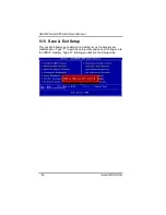
Page 56: ...BIOS Utility 50 5 15 Save Exit Setup This section allows you to determine whether or not to accept your modifications Type Y to quit the setup utility and save all changes into the CMOS memory Type N...

Page 57: ...tility 51 5 16 Exit Without Saving Select this option to exit the Setup utility without saving changes you have made in this session Type Y and it will quit the Setup utility without saving your modif...

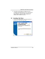
Page 58: ...comes with the SBC81203 Series package The auto run function of drivers will guide you to install the utilities and device drivers under a Windows system You can follow the onscreen instructions to i...

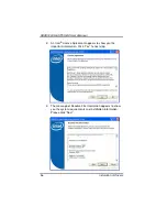
Page 59: ...LGA775 SBC User s Manual Installation of Drivers 53 2 An Intel License Agreement appears to show you the important information Click Yes to next step 3 Please wait while running the following setup op...

Page 60: ...SBC81203 LGA775 SBC User s Manual Instalation of Drivers 54 4 Click Finish to complete the setup process...

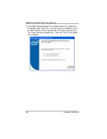
Page 61: ...llation is completed Please click Yes I want to restart my computer now if you don t need to install any other drivers Otherwise please click No I will restart my computer later and go on next step 6...

Page 62: ...of Drivers 56 2 An Intel License Agreement appears to show you the important information Click Yes to next step 3 The message of Readme File Information appears to show you the system requirements an...

Page 63: ...SBC81203 LGA775 SBC User s Manual Installation of Drivers 57 4 Please wait while running the following setup operations 5 When this message appears please click Next...

Page 64: ...be asked to reboot your computer when the installation is completed Please click Yes I want to restart my computer now if you don t need to install any other drivers Otherwise please click No I will r...

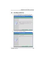
Page 65: ...User s Manual Installation of Drivers 59 6 3 Installing LAN Driver 1 Run the InstallShield Wizard for Ethernet from the driver directory in your driver CD Click Next to next step 2 Click Install to st...

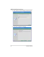
Page 66: ...SBC81203 LGA775 SBC User s Manual Instalation of Drivers 60 3 Please wait while running the following installation operation 4 Click Finish to complete the installation...

Page 67: ...Installation of Drivers 61 6 4 Installing Audio Driver 1 Run the InstallShield Wizard program from the driver directory in your driver CD Please wait while running the following operation 2 When this...

Page 68: ...n of Drivers 62 3 You will be asked to reboot your computer when the InstallShield Wizard is installed Please click Yes I want to restart my computer now or No I will restart my computer later and nex...

Page 69: ...SBC81203 LGA775 SBC User s Manual Installation of Drivers 63 MEMO...

Page 70: ...SBC81203 LGA775 SBC User s Manual Watch Dog Timer 64 A p p e n d i x A Watch Dog Timer Please follow the below WDT process for setup the WDT function...

Page 71: ...SBC81203 LGA775 SBC User s Manual Watch Dog Timer 65 MEMO...

Page 72: ...i x B PCI IRQ Routing Digital I O Software Programming PICMG PCI IRQ Routing Device ID Slot Int PCI Slot 0 31 0 BCDA PCI Slot 1 30 1 CDAB PCI Slot 2 29 2 DABC PCI Slot 3 28 3 ABCD On Board Device IRQ...

Page 73: ...SBC81203 LGA775 SBC User s Manual PCI IRQ Routing 67 MEMO...

Page 74: ...he SATA RAID function that allows you to combine four SATA II disk drives into RAID volume configurations The RAID configurations help you increase disk access speed RAID0 or withstand a single disk d...

Page 75: ...SBC81203 LGA775 SBC User s Manual What Is SATA RAID Function 69 2 RAID1 Mirroring 3 RAID5 Block Interleaved Distributed Parity...

Page 76: ...SBC81203 LGA775 SBC User s Manual Memory I O Address 70 A p p e n d i x D Memory I O Address...

Page 77: ...SBC81203 LGA775 SBC User s Manual Memory I O Address 71 MEMO...

Reviews: