UST200-83H-FL
User’s Manual
5
Introduction
1.2.14
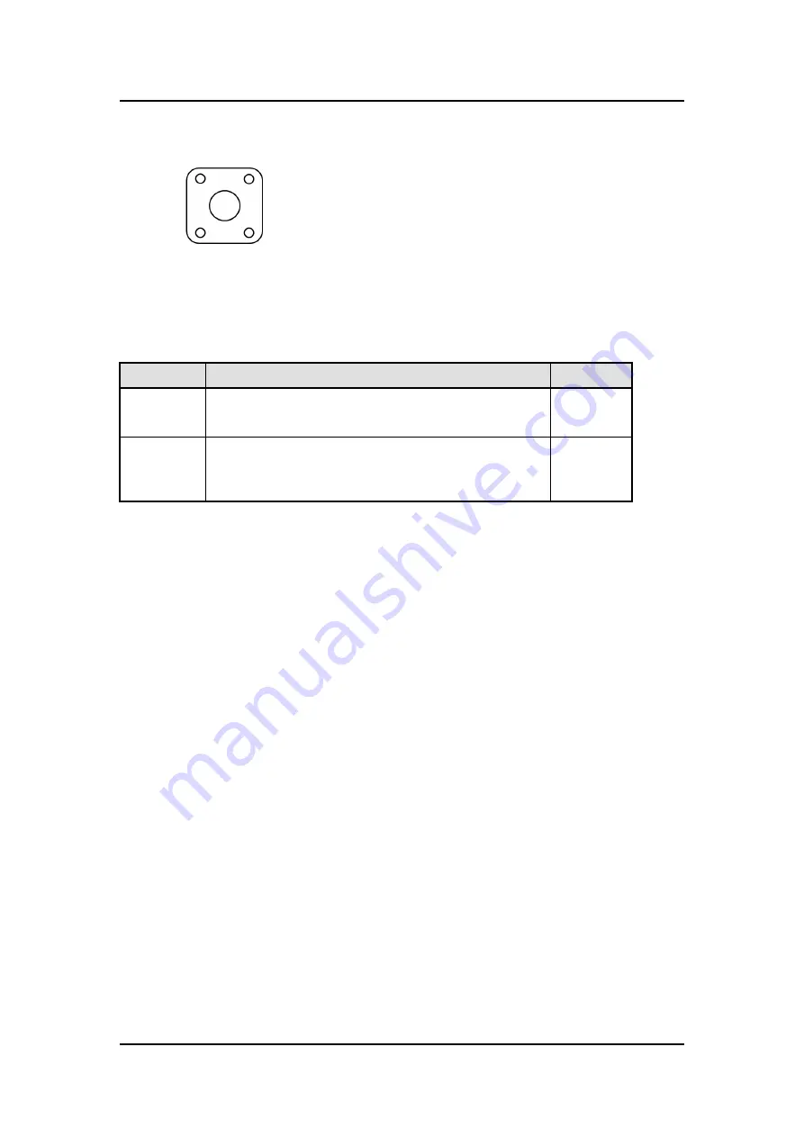
Restore BIOS Optimal Defaults (SW1)
Press the tact switch (SW 1) 4 seconds to restore optimal BIOS defaults.
1.2.15
System LED
The table below summarizes the functional descriptions of the LED indicators and their
corresponding colors.
LED Name
Description
Color
ACT
Indicates storage status. The LED flashes when storage is
being accessed.
Orange
PWR
Indicates power status. When the DC input is acceptable, the
LED will turn on.
Green
1.2.16
Operation Temperature
Wide temperature -40
0
C ~ +70
0
C
1.2.17
Storage Temperature
-40
0
C ~ +85
0
C
1.2.18
Humidity
0% ~ 95% (non-condensation)
1.2.19
Weight
0.3 kg
1.2.20
Dimensions
31mm
(1.22”) (W) x100mm (3.93”) (D) x125mm (4.92”) (H)
Summary of Contents for UST200-83H-FL
Page 1: ...UST200 83H FL Robust DIN rail Fanless Embedded System User s Manual ...
Page 8: ...viii This page is intentionally left blank ...
Page 18: ...UST200 83H FL User s manual Introduction 10 This page is intentionally left blank ...
Page 30: ...UST200 83H FL User s manual 22 Hardware Installation This page is intentionally left blank ...
Page 34: ...UST200 83H FL Series User s Manual 26 AMI UEFI BIOS Utility ...
Page 41: ...UST200 83H FL User s Manual AMI UEFI BIOS Utility 33 ...
Page 43: ...UST200 83H FL User s Manual AMI UEFI BIOS Utility 35 ...
Page 44: ...UST200 83H FL Series User s Manual 36 AMI UEFI BIOS Utility ...
Page 46: ...UST200 83H FL Series User s Manual 38 AMI UEFI BIOS Utility ...
Page 47: ...UST200 83H FL User s Manual AMI UEFI BIOS Utility 39 ...
Page 48: ...UST200 83H FL Series User s Manual 40 AMI UEFI BIOS Utility ...


