background image

UST200-83H-

FL Series User’s Manual 

40 

AMI UEFI BIOS Utility 


Summary of Contents for UST200-83H-FL

Page 1: ...UST200 83H FL Robust DIN rail Fanless Embedded System User s Manual ...

Page 2: ... usefulness of any information in this document Axiomtek does not make any commitment to update the information in this manual Axiomtek reserves the right to change or revise this document and or product at any time without notice No part of this document may be reproduced stored in a retrieval system or transmitted in any form or by any means electronic mechanical photocopying recording or otherw...

Page 3: ...he storage temperature is below 45 or above 85 It may damage the equipment 7 Do not open the system s back cover If opening the cover for maintenance is a must only a trained technician is allowed to do so Integrated circuits on computer boards are sensitive to static electricity To avoid damaging chips from electrostatic discharge observe the following precautions Before handling a board or integ...

Page 4: ...t for the computer please read and understand the details below fully When you need to clean the device please rub it with a piece of dry cloth 1 Be cautious of the tiny removable components when you use a vacuum cleaner to absorb the dirt on the floor 2 Turn the system off before you start to clean up the computer or any components 3 Never drop the components inside the computer or get circuit bo...

Page 5: ...cohol You may moisten a piece of cloth a bit with some water or rubbing alcohol and rub it on the computer Unknown solvents may be harmful to the plastics parts Vacuum cleaner Vacuuming the dust dirt hair cigarette particles and other particles out of a computer can be one of the best methods of cleaning a computer Over time these items can restrict the airflow in a computer and cause circuitry to...

Page 6: ...f Axiomtek Co Ltd IBM PC AT PS 2 VGA are trademarks of International Business Machines Corporation Intel and Pentium are registered trademarks of Intel Corporation MS DOS Microsoft C and QuickBASIC are trademarks of Microsoft Corporation VIA is a trademark of VIA Technologies Inc SST is a trademark of Silicon Storage Technology Inc UMC is a trademark of United Microelectronics Corporation Other br...

Page 7: ...1 3 Dimensions 7 1 4 I O Outlets 8 SECTION 2 HARDWARE INSTALLATION 11 2 1 Installing the Memory Module 11 2 2 Installing the mSATA 13 2 3 Installing the Wireless Module 14 2 4 Installing the DIN rail Kit 20 2 5 Installing the Wall Mount Kit Optional 21 SECTION 3 AMI UEFI BIOS UTILITY 23 3 1 Entering Setup 23 3 2 The Main Menu 24 3 3 Advanced Features 25 3 4 Chipset Feature 43 3 5 Security 44 3 6 B...

Page 8: ...viii This page is intentionally left blank ...

Page 9: ...ial automation Its compact size along with wall mount and DIN rail mounting support also allows for easy installation into control cabinets Pre installed with Linux and Windows 10 the UST200 83H FL provides programmers with a friendly environment for developing application software at a lower cost By supporting mSATA the UST200 83H FL also serves as a perfect field control monitoring system soluti...

Page 10: ... DDR3L 204 pin SO DIMM 1 35V slot Supports 1866MHz max up to 8GB 1 2 4 Display One slim type 15 pin D Sub connector as VGA connector Supports VGA standards up to 1920x1200 60Hz 1 2 5 Ethernet Ports LAN chip Intel Ethernet Controller Intel I211 2 x RJ 45 connectors support 10 100 1000 Base T Ethernet with 1 5KV magnetic isolated protection 1 2 6 Storage 1 x mSATA 1 2 7 Wireless 1 x Full size Mini C...

Page 11: ...5 mode Serial Port Pin Define DB9 Male as below Supports High Speed Mode115 2 Kbps Up to 1 5 Mbps COM Pin RS 232 RS 422 RS 485 1 DCD TX Data 2 RXD TX Data 3 TXD RX 4 DTR RX 5 GND GND GND 6 DSR 7 RTS 8 CTS 9 RI 1 2 10 Power Power Input DC Terminal block Wide range 9 36V OVP and Reverse protection Pin Signal 1 2 3 IGN Pin Signal USB2 0 Port 1 Pin Signal USB2 0 Port 2 1 VCC 5 VCC 2 D0 6 D1 3 D0 7 D1 ...

Page 12: ... The voltage of TTL is 5V The programming is as follow I O sink current is 8 10mA Input Output is programmable Pin Signal 1 DIO0 2 DIO1 3 DIO2 4 DIO3 5 DIO4 6 DIO5 7 DIO6 8 DIO7 9 GND 1 2 12 CANBus CANBus SKU Pin Signal 1 NC 2 CAN L 3 GND 4 NC 5 GND 6 NC 7 CAN H 8 NC 9 NC 1 2 13 WatchDog Timer WDT 1 255 seconds or minutes up to 255 levels ...

Page 13: ...rs and their corresponding colors LED Name Description Color ACT Indicates storage status The LED flashes when storage is being accessed Orange PWR Indicates power status When the DC input is acceptable the LED will turn on Green 1 2 16 Operation Temperature Wide temperature 40 0 C 70 0 C 1 2 17 Storage Temperature 40 0 C 85 0 C 1 2 18 Humidity 0 95 non condensation 1 2 19 Weight 0 3 kg 1 2 20 Dim...

Page 14: ...ctor COM1 COM SKU 1 x 9 pin D Sub male connector CANBus 2 0A B CAN SKU 1 x 15 pin D Sub female connector for VGA 2 x 10 100 1000 Base T RJ 45 with 1 5KV magnetic isolated protection 2 x USB 2 0 ports 1 x DC power input with terminalblock 1 x 9 pin D Sub female connector for DIO 2 x Antenna holes ...

Page 15: ...UST200 83H FL User s Manual 7 Introduction 1 3 Dimensions The following diagrams show you the dimensions and outlines of the UST200 83H FL ...

Page 16: ...UST200 83H FL User s manual Introduction 8 1 4 I O Outlets The following figures show you the I O outlets on the front view and top view of the UST200 83H FL ...

Page 17: ...UST200 83H FL User s Manual 9 Introduction The following figures show you the I O outlets on the front view and bottom view of the UST200 83H FL ...

Page 18: ...UST200 83H FL User s manual Introduction 10 This page is intentionally left blank ...

Page 19: ...ious hardware configurations such as memory modules and mSATA drives Chapter 2 will show you how to install the hardware 2 1 Installing the Memory Module Step 1 Turn off the system Step 2 Loosen all screws of the cover and remove the cover from the system Step 3 Put the thermal pad on the memory module to increase cooling effect ...

Page 20: ...gold contact into the slot and push the module down Step 5 The memory module is locked by two latches on the sides We strongly recommend using LDC737 silicone on both sides of the memory for optimal protection against vibration Step 6 Put the cover back onto the system and fasten all screws tight to close the chassis ...

Page 21: ...ual Hardware Installation 13 2 2 Installing the mSATA Step 1 Turn off the system Step 2 Loosen all screws of the cover and remove the cover from the system Step 3 Insert the mSATA into the slot with the marking mSATA USB PCIe ...

Page 22: ...p 4 Fasten the screws tightly Step 5 Put the cover back onto the system and fasten all screws tight to close the chassis 2 3 Installing the Wireless Module Step 1 Turn off the system Step 2 Loosen all screws of the cover and remove the cover from the system ...

Page 23: ... Installation 15 Step 3 Slide the SIM slot upward to unlock and lift the SIM slot Figure 3 1 insert the SIM card and put it back down Figure 3 2 and then slide the SIM slot downward to lock it up Figure3 3 Figure 3 1 Figure 3 2 Figure 3 3 ...

Page 24: ...UST200 83H FL User s manual 16 Hardware Installation Step 4 Insert the wireless module into the slot with the marking USB PCIe Step 5 Insert the LTE module and screw it tight ...

Page 25: ...UST200 83H FL User s Manual Hardware Installation 17 Step 6 Remove the plug cover from the chassis Step 7 Connect the RF cable to the connector of the LTE module marked by MAIN ...

Page 26: ...ntenna nut and gasket from the LTE kit package Figure 8 1 Make the end of the RF cable through the antenna hole Figure 8 2 Finally screw the end of the RF cable tightly with the antenna nut and gasket Figure 8 3 Figure 8 1 Figure 8 2 Figure 8 3 Step 9 Screw the RF antenna tight ...

Page 27: ...ST200 83H FL User s Manual Hardware Installation 19 Step 10 Put the cover back onto the system and fasten all screws tight to close the chassis Note Use only standard size SIM cards as illustrated below ...

Page 28: ...tion 2 4 Installing the DIN rail Kit The UST200 83H FL provides DIN rail mount as illustrated below Step 1 Prepare the DIN rail mount assembling components screws and bracket ready Step 2 Assembly the bracket to the system and fasten all screws tight ...

Page 29: ...g the Wall Mount Kit Optional The UST200 83H FL provides a wall mount kit that customers can install as illustrated below Step 1 Prepare the wall mount assembling components screws and bracket ready Step 2 Assemble the bracket to the system and fasten all screws tight ...

Page 30: ...UST200 83H FL User s manual 22 Hardware Installation This page is intentionally left blank ...

Page 31: ... parameters are stored in a flash backup to save the Setup information whenever the power is turned off 3 1 Entering Setup To enter the setup screens follow the steps below 1 Turn on the computer and press the Del keyimmediately 2 After you press the Del key the main BIOS setup menu displays You can access the other setup screens from the main BIOS setup menu such as the Advanced and Chipset menus...

Page 32: ... a couple of Exit options for your selection Use Select Screen Keys or Move Keys to select the Setup Page you intend to configure and then press Enter to accept or enter its sub menu System Date The date format is day month date year System Time This item shows current time of your system with the format hour minute second The time is calculated based on the 24 hour military time clock For example...

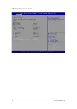
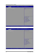
Page 33: ...o configure and improve your system or to set up some system features according to your preference You can select any of the items in the left frame of the screen to go to the sub menus CPU Configuration Scroll to this item and press Enter to view the CPU Configuration information Please refer below graphics ...

Page 34: ...UST200 83H FL Series User s Manual 26 AMI UEFI BIOS Utility ...

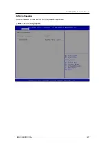
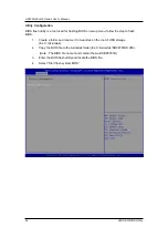
Page 35: ...UST200 83H FL User s Manual AMI UEFI BIOS Utility 27 SATAConfiguration Scroll to this item to view the SATA Configuration information Please refer to below graphics ...

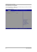
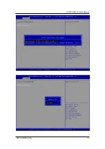
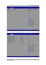
Page 36: ...r s Manual 28 AMI UEFI BIOS Utility PCIe mSATA Mini Card Configuration You can choose the PCIe or mSATA function for the Mini Card mode selectable via the BIOS menu The default setting is mSATA mode Please refer below graphics ...

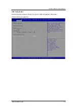
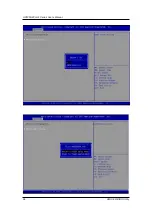
Page 37: ...UST200 83H FL User s Manual AMI UEFI BIOS Utility 29 USB Configuration Scroll to this item and press Enter to view the USB Configuration information Please refer below graphics ...

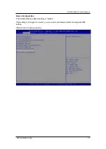
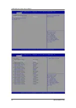
Page 38: ...UST200 83H FL Series User s Manual 30 AMI UEFI BIOS Utility H W Monitor Scroll to this item and press Enter to view the hardware status items under monitoring please refer below graphics ...

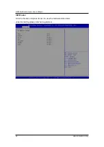
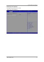
Page 39: ...UST200 83H FL User s Manual AMI UEFI BIOS Utility 31 F81804 Super IO Configuration The default setting for Serial Port 1 is CAN Please refer to below graphics ...

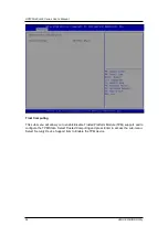
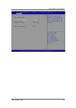
Page 40: ...ity Trust Computing This sub menu will allow you to enable disable Trusted Platform Module TPM support and to configure the TPM State Select Trusted Computing and press Enter to access the sub menu Select Security Device Support item to Enable the TPM device ...

Page 41: ...UST200 83H FL User s Manual AMI UEFI BIOS Utility 33 ...

Page 42: ...etup menu follow the step to flash BIOS 1 Create a folder and rename it to Axiomtek on the root of USB storage Ex X Axiomtek 2 Copy the BIOS file to the Axiomtek folder Ex X Axiomtek SBC8783HX 003 Note The BIOS file name must contain the wordSBC8783H 3 Enter the BIOS flash utility and locate the BIOS file 4 Select Start flash system BIOS ...

Page 43: ...UST200 83H FL User s Manual AMI UEFI BIOS Utility 35 ...

Page 44: ...UST200 83H FL Series User s Manual 36 AMI UEFI BIOS Utility ...

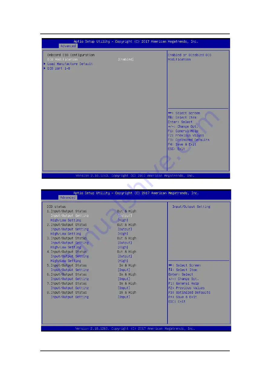
Page 45: ...anual AMI UEFI BIOS Utility 37 Device Configuration The DIO Modification default setting is disable If the setting is changed to enable you can load manufacture default and program DIO setting Please refer to below graphics ...

Page 46: ...UST200 83H FL Series User s Manual 38 AMI UEFI BIOS Utility ...

Page 47: ...UST200 83H FL User s Manual AMI UEFI BIOS Utility 39 ...

Page 48: ...UST200 83H FL Series User s Manual 40 AMI UEFI BIOS Utility ...

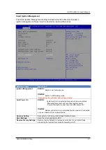
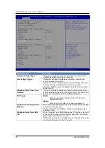
Page 49: ...after setting is saved Auto Power On Enabled System will turn on automatically under below conditions Manually disconnect and reconnect system power Power interruption power resumes after power fail Disabled System will not turn on automatically when power is connected or power resumes from a power failure Advance Setting Set system on off timing and voltage threshold levels Save Settings Save the...

Page 50: ...source voltage drops below the value defined in Low Voltage Trigger The system will be forced to turn off once timer completes countdown IGN Trigger Enable IGN signal will trigger System Turn On Delay and Shutdown Delay Disable IGN signal will not affect any power management System Turn On Delay Timer IGN On When receiving the IGN signal the system will be turned on after setup time is counted dow...

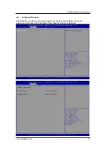
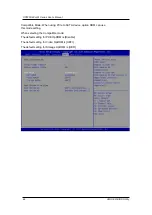
Page 51: ...ser s Manual AMI UEFI BIOS Utility 43 3 4 Chipset Feature The Chipset menu allows users to change the advanced chipset settings Users can select any of the items in the left frame of the screen to go to the sub menus ...

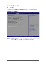
Page 52: ...users to enhance system security by setting an administrator password No password has been set in the default setting Please refer to below graphics Note The BIOS default has no password The user must remember the password after creating one If the user forgets the password RMA is the only solution ...

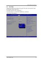
Page 53: ...ode The Boot menu allows users to change boot options of the system providing UEFI Legacy and Compatible modes to select from The default setting boot mode is UEFI Mode The default setting for Launch UEFI PXE OpROM policy is Disabled Please refer to below graphics ...

Page 54: ...ity Compatible Mode When using PCIe to SATA device option ROM can use this mode setting When selecting the Compatible mode The default setting for PXE OpROM is Disable The default setting for Video OpROM is UEFI The default setting for Storage OpROM is UEFI ...

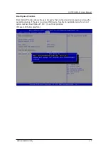
Page 55: ...ities Boot Option Priorities allows the user to specify the boot device priority sequence among the available devices if the user is using a USB device Specify an available device for a boot option number Boot Option 1 2 to set boot priorities Please refer below graphics ...

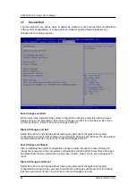
Page 56: ...tion to quit Setup without making any permanent changes to the system configuration and return to Main Menu Select Discard Changes and Exit from the Save Exit menu and press Enter Select Yes to discard changes and exit Save Changes and Reset After completing the system configuration changes select this option to leave Setup and reboot the computer so the new system configurations will take effect ...

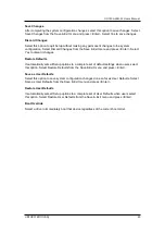
Page 57: ...e Defaults It automatically sets all Setup options to a complete set of default settings when users select this option Select Restore Defaults from the Save Exit menu and press Enter Save as User Defaults Select this option to save system configuration changes done so far as User Defaults Select Save as User Defaults from the Save Exit menu and press Enter Restore User Defaults It automatically se...

Reviews: