AXIS A9188 Network I/O Relay Module
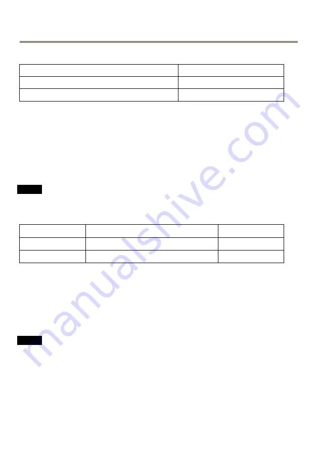
The following table shows the available power after connection of the 0.3 A device in the example.
Power source
Available power
Power over Ethernet802.3at Type 2 Class 4
12 – 3.6 = 8.4 W
8–28 V DC
12 – 3.6 = 8.4 W
The DC output on the following connectors are considered as power outputs:
•
DC Power Out Connector
•
Supervised I/O Connector
For connector specifications, see
Wire Area
NO
NO
NOTICE
TICE
TICE
Each wire shall have an conductor cross-sectional area that corresponds to an conductor
gauge range of AWG 28–16 (CSA) or AWG 22–14 (cUL/UL). Select cables in compliance
with your local regulations.
AWG
Diameter
mm (in)
Area
mm
2
28–16
0.321–1.29 (0.0126–0.0508)
0.0810–1.31
22–14
0.644–1.63 (0.0253–0.0641)
0.326–2.08
Connectors
For information about the connectors’ positions, see
.
The following section describes the connectors’ technical specifications.
Network Connector
NO
NO
NOTICE
TICE
TICE
The product shall be connected using a shielded network cable (STP). All cables connecting
the product to the network shall be intended for their specific use. Make sure that the
network devices are installed in accordance with the manufacturer’s instructions. For
information about regulatory requirements, see
Electromagnetic compatibility (EMC) on
.
RJ45 Ethernet connector. Use Category 5e cables or higher.
22
Summary of Contents for A9188
Page 1: ...AXIS A9188 Network I O Relay Module Installation Guide Full Reference...
Page 4: ......
Page 8: ...8...
Page 29: ...29...


