background image

AXIS Q1775-E Network Camera

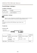
Caractéristiques techniques

Conditions d’utilisation

Température

Humidité

De -40 °C à 50 °C
(-40 °F à 122 °F)

Humidité relative de 10 à 100 %
(sans condensation)

Consommation électrique

A

A

AVIS

VIS

VIS

Utilisez une source d'alimentation limitée (LPS) dont la puissance de sortie nominale est
limitée à ≤ 100 W ou dont le courant de sortie nominal est limité à ≤5 A.

PoE

Alimentation par Ethernet (PoE) IEEE 802.3at Type 2 Classe 4 max.
25,5 W

Connecteurs

Connecteur audio

Connecteurs
audio 3,5 mm (stéréo)

1

2

3

1 Pointe

2 Anneau

3 Manchon

Entrée audio

Équilibré : Entrée micro/ligne
point chaud

Déséquilibré : Entrée
micro/ligne

Équilibré : Entrée micro/ligne
point froid

Déséquilibré : Inutilisé

Masse

Sortie audio

Sortie ligne (mono)

Masse

34

Summary of Contents for Q1775-E

Page 1: ...AXIS Q1775 E Network Camera ENGLISH FRAN AIS DEUTSCH ITALIANO ESPAN L Installation Guide...

Page 2: ...es other countries or both Also miniSD microSD miniSDHC microSDHC microSDXC are all trademarks or registered trademarks of SD 3C LLC in the United States other countries or both Regulatory Information...

Page 3: ...hold or commercial waste Directive 2012 19 EU on waste electrical and electronic equipment WEEE is applicable in the European Union member states To prevent potential harm to human health and the envi...

Page 4: ......

Page 5: ...a hazardous situation which if not avoided could result in death or serious injury CAUTION Indicates a hazardous situation which if not avoided could result in minor or moderate injury NO NO NOTICE T...

Page 6: ...be provided by Axis or a third party Use only spare parts provided by or recommended by Axis Do not attempt to repair the product by yourself Contact Axis support or your Axis reseller for service mat...

Page 7: ...f explosion if the battery is incorrectly replaced Replace only with an identical battery or a battery which is recommended by Axis Dispose of used batteries according to local regulations or the batt...

Page 8: ...8...

Page 9: ...for the installation are in order See page 9 2 Study the hardware overview See page 10 3 Study the specifications See page 15 4 Install the hardware See page 18 5 Access the product See page 20 Packa...

Page 10: ...onnector blocked in AXIS Q1775 E 4 RS 485 422 connector 5 I O connector 6 Control button 7 Network indicator LED 8 Power indicator LED 9 Audio in 10 SD card slot 11 Audio out 12 CVBS button 13 Network...

Page 11: ...Top cover 4 Network camera 5 Network connector PoE 6 Safety wire tab 7 Cable hole 8 Bottom cover screws 4x 9 Heater Caution May be hot 10 Bottom cover 11 Cable cover 12 Gasket 13 Network cable route...

Page 12: ...storing settings Note The Network LED can be disabled so that it does not flash when there is network traffic To configure go to Setup System Options Ports Devices LED See the online help for more inf...

Page 13: ...reen Continuous beep Level Flashing green Fast interval Almost level Flashing orange Medium interval Not level Flashing red Slow interval Far from level Connectors and Buttons For specifications and o...

Page 14: ...er System Options Ports Devices Note The I O connector is connected to the housing fan heater on delivery In the case of a fan or heater error an input signal will be triggered in the camera Set up an...

Page 15: ...st levelling of the camera The camera is level when the buzzer beeps continuously Connecting to an AXIS Video Hosting System service or AXIS Internet Dynamic DNS Service For more information about the...

Page 16: ...onnectors stereo 1 2 3 1 Tip 2 Ring 3 Sleeve Audio Input Balanced Hot signal Microphone Line in Unbalanced Microphone Line in Balanced Cold signal Microphone Line in Unbalanced Unused Ground Audio Out...

Page 17: ...ction against voltage transients 0 to max 30 V DC open drain 100 mA RS485 422 Connector Two 2 pin terminal blocks for RS485 RS422 serial interface The serial port can be configured to support Two wire...

Page 18: ...Connection Diagrams I O Connector 1 2 A B 1 0 V DC 2 DC output 12 V max 50 mA A I O configured as input B I O configured as output Install the Hardware Install Wall Bracket To install the wall bracke...

Page 19: ...using screws and plugs appropriate for the material e g wood metal sheet rock stone Route the Network and Other Cables Note Check against the hardware overview image see page 10 while following the st...

Page 20: ...ications are free and can be downloaded from www axis com techsup The product can be used with most operating systems and browsers The recommended browsers are Internet Explorer with Windows Safari wi...

Page 21: ...m It is also possible to reset parameters to factory default via the web interface Go to Setup System Options Maintenance Further Information The User Manual is available at www axis com Visit www axi...

Page 22: ...22...

Page 23: ...dangereuse qui si elle n est pas vit e pourrait entra ner le d c s ou des blessures graves ATTENTION Indique une situation dangereuse qui si elle n est pas vit e pourrait entra ner des blessures l g r...

Page 24: ...aract ristiques techniques du produit Ils peuvent tre fournis par Axis ou un tiers Utiliser uniquement les pi ces de rechange fournies ou recommand es par Axis Ne pas essayer de r parer ce produit par...

Page 25: ...e www axis com techsup et obtenir de l aide AVERTISSEMENT Risque d explosion si la batterie est remplac e de fa on incorrecte Remplacez la uniquement par une batterie identique ou une batterie recomma...

Page 26: ...26...

Page 27: ...inclus dans l emballage Cf page 27 2 Consultez la description du mat riel Cf page 28 3 tudiez les caract ristiques Cf page 34 4 Installez le mat riel Cf page 36 5 Utilisez le produit Cf page 38 Conten...

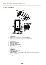
Page 28: ...n bloqu dans l AXIS Q1775 E 4 Connecteur RS 485 422 5 Connecteur E S 6 Bouton de commande 7 Voyant DEL r seau 8 Voyant DEL d alimentation 9 Entr e audio 10 Emplacement pour carte SD 11 Sortie audio 12...

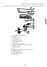
Page 29: ...u 5 Connecteur r seau PoE 6 Patte de fil de s curit 7 Trou de c ble 8 Vis du couvercle inf rieur x4 9 R gulateur de chaleur Attention Peut tre chaud 10 Couvercle inf rieur 11 Couvercle de c ble 12 Joi...

Page 30: ...ge et lors de la restauration des param tres Note Le voyant de r seau peut tre d sactiv afin qu il ne clignote pas en cas de trafic r seau Pour ce faire rendez vous dans Setup System Options Ports Dev...

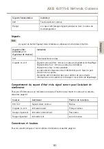
Page 31: ...d alarmes seront d clench s par le biais du port d entr e de la cam ra Contactez votre revendeur Axis pour obtenir de plus amples informations sur les pi ces de rechange et les services de d pannage C...

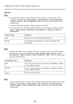
Page 32: ...ve View Vid o en direct ou par une r gle d action La sortie est consid r e comme tant active comme indiqu dans System Options Ports Devices Options du syst me Ports et dispositifs si le dispositif d a...

Page 33: ...ton de commande consultez Aper u du mat riel page 28 Le bouton de commande permet de r aliser les op rations suivantes R initialisation du produit aux param tres d usine par d faut Cf page 38 Connexio...

Page 34: ...t la puissance de sortie nominale est limit e 100 W ou dont le courant de sortie nominal est limit 5 A PoE Alimentation par Ethernet PoE IEEE 802 3at Type 2 Classe 4 max 25 5 W Connecteurs Connecteur...

Page 35: ...e entr e ou sortie 3 4 Sortie num rique Connect e la broche 1 lorsqu elle est activ e flotte d connect e lorsqu elle est d sactiv e Si vous l utilisez avec une charge inductive par exemple un relais u...

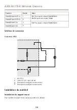
Page 36: ...RS485 RS422 TX A 3 RS485 RS422 TX B 4 TX Pour duplex int gral RS485 RS422 Sch mas de connexion Connecteur d E S 1 2 A B 1 0 V CC 2 Sortie CC 12 V maxi 50 mA A Entr e sortie configur e comme entr e B...

Page 37: ...du support Laissez environ 30 cm 11 8 de c ble pour la connexion de la cam ra 3 Fixez le support mural au mur au plafond ou sur le poteau l aide de vis et de chevilles adapt es au mat riau bois m tal...

Page 38: ...ns des environnements lectriques exigeants doivent tre blind s STP et destin s leur usage sp cifique Utilisez le produit Si vous souhaitez rechercher des produits Axis sur le r seau ou leur affecter d...

Page 39: ...tion pour attribuer une adresse IP configurer le mot de passe et acc der au flux de donn es vid o Il est galement possible de r tablir les param tres d usine partir de l interface Web Acc dez Setup Sy...

Page 40: ...40...

Page 41: ...ation hin welche falls nicht verhindert zu Tod oder schweren Verletzungen f hren kann VORSICHT Weist auf eine gef hrliche Situation hin welche falls nicht verhindert zu geringf giger oder m iger Verle...

Page 42: ...xis oder Drittanbietern erh ltlich Verwenden Sie ausschlie lich Ersatzteile die von Axis bereitgestellt oder empfohlen werden Versuchen Sie nicht das Produkt selbstst ndig zu reparieren Wenden Sie sic...

Page 43: ...i fehlerhaftem Batteriewechsel Die Batterie darf nur durch eine identische Batterie oder eine von Axis empfohlene Batterie ersetzt werden Verbrauchte Batterien sind gem den rtlichen Vorschriften oder...

Page 44: ...44...

Page 45: ...te 45 2 Machen Sie sich mit der Hardware bersicht vertraut Siehe Seite 46 3 Machen Sie sich mit den technischen Daten vertraut Siehe Seite 52 4 Installieren Sie die Hardware Siehe Seite 54 5 Greifen S...

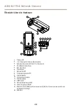
Page 46: ...chluss bei AXIS Q1775 E blockiert 4 RS 485 422 Anschluss 5 E A Anschluss 6 Steuertaste 7 Netzwerk LED 8 Stromversorgungs LED 9 Audioeingang 10 SD Kartensteckplatz 11 Audioausgang 12 CVBS Taste 13 Netz...

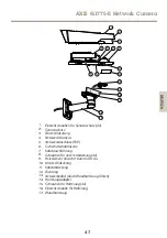
Page 47: ...amera 5 Netzwerkanschluss PoE 6 Sicherheitsdrahtlasche 7 Kabeldurchf hrung 8 Schrauben f r untere Abdeckung 4x 9 Heizelement Vorsicht Kann hei sein 10 Untere Abdeckung 11 Kabelabdeckung 12 Dichtung 13...

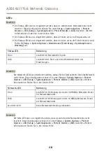
Page 48: ...beim Wiederherstellen der Einstellungen Beachten Die Netzwerk LED kann deaktiviert werden sodass Sie bei Datenverkehr ber das Netzwerk nicht blinkt Diese Konfiguration k nnen Sie unter Setup System O...

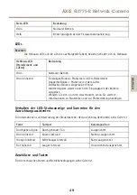
Page 49: ...en Eingangsport der Kamera ausgel st Wenden Sie sich an Ihren Axis H ndler wenn Sie weitere Informationen zu Ersatzteilen und zur Probleml sung ben tigen Verhalten der LED Statusanzeige und Summton f...

Page 50: ...der Seite Live View oder durch eine Aktionsregel aktiviert werden Der Ausgang wird als aktiv siehe System Options Ports Devices Systemoptionen Anschl sse Ger te angezeigt wenn das Alarmmeldeger t akt...

Page 51: ...elle bersicht ber die Hardware auf Seite 46 Die Steuertaste hat folgende Funktionen Zur cksetzen des Produkts auf die Werkseinstellungen Siehe Seite 57 Verbinden mit einem AXIS Video Hosting System Se...

Page 52: ...r Nennausgangsleistung von 100 W oder einem dauerhaft auf 5 A begrenzten Nennausgangsstrom PoE Power over Ethernet PoE IEEE 802 3at Typ 2 Klasse 4 max 25 5 W Anschl sse Audioanschl sse 3 5 mm Audioans...

Page 53: ...figurierbar Ein oder Ausgang 3 4 Digitalausgang bei Aktivierung mit Pin 1 verbunden wenn deaktiviert frei nicht verbunden Bei Verwendung mit einer induktiven Last z B einem Relais muss parallel zur La...

Page 54: ...albduplex RS485 RS422 TX A 3 RS485 RS422 TX B 4 TX RS485 RS422 f r Vollduplex Anschlussschaltbilder E A Anschluss 1 2 A B 1 0 V DC 2 DC Ausgang 12 V max 50 mA A E A als Eingang konfiguriert B E A als...

Page 55: ...zwerkkabel durch die Wandhalterung und den Wandhalterungsadapter Lassen Sie zum Anschlie en der Kamera ca 30 cm Kabel frei 3 Montieren Sie die Wandhalterung an einer Wand einer Decke oder einem Mast S...

Page 56: ...NWEIS HINWEIS HINWEIS Aufgrund rtlicher Vorschriften oder den umweltbedingten und elektrischen Bedingungen unter denen das Produkt verwendet wird kann ein abgeschirmtes Netzwerkkabel STP empfehlenswer...

Page 57: ...ige gr n leuchtet Das Produkt wurde auf die Werkseinstellungen zur ckgesetzt Wenn kein DHCP Server im Netzwerk verf gbar ist lautet die Standard IP Adresse 192 168 0 90 5 Verwenden Sie die Software To...

Page 58: ...58...

Page 59: ...ENZA Indica una situazione pericolosa che se non evitata pu provocare la morte o lesioni gravi ATTENZIONE Indica una situazione pericolosa che se non evitata pu provocare lesioni medie o minori A A AV...

Page 60: ...e forniti da Axis o da terze parti Utilizzare solo parti di ricambio fornite o consigliate da Axis Non tentare di riparare il dispositivo da soli Contattare l assistenza o il rivenditore Axis per ques...

Page 61: ...splosione se la batteria viene sostituita in modo errato Sostituire solo con una batteria identica o una batteria consigliata da Axis Smaltire le batterie usate in base alle normative locali o alle is...

Page 62: ...62...

Page 63: ...per l installazione siano in ordine Consultare pagina 63 2 Studiare la descrizione dell hardware Consultare pagina 64 3 Studiare le specifiche Consultare pagina 70 4 Installare l hardware Consultare...

Page 64: ...ne bloccato in AXIS Q1775 E 4 Connettore RS 485 422 5 Connettore I O 6 Pulsante di comando 7 Indicatore LED di rete 8 Indicatore LED di alimentazione 9 Ingresso audio 10 Slot per scheda SD 11 Uscita a...

Page 65: ...rete PoE 6 Linguetta per il cavo di sicurezza 7 Foro per il cavo 8 Viti del coperchio inferiore 4x 9 Riscaldatore Attenzione Pu essere caldo 10 Coperchio inferiore 11 Coperchio dei cavi 12 Guarnizione...

Page 66: ...ssa durante l avvio e quando si ripristinano le impostazioni Nota Il LED di rete pu essere disattivato in modo da non lampeggiare in caso di traffico di rete Per configurarlo selezionare Setup System...

Page 67: ...o la porta di input della telecamera Contattare il rivenditore Axis per informazioni su pezzi di ricambio e risoluzione dei problemi Comportamento del LED di stato e del segnale acustico per Levelling...

Page 68: ...e tramite l opzione Action Rule regola di azione L uscita verr visualizzata come attiva visualizzata in Opzioni di Sistema Porte e Dispositivi se il dispositivo di allarme attivato Ingresso digitale I...

Page 69: ...oramica dell hardware alla pagina 64 Il pulsante di comando viene utilizzato per Ripristino del dispositivo alle impostazioni predefinite di fabbrica Consultare pagina 75 Collegamento a un servizio AX...

Page 70: ...i uscita nominale limitata a 100 W o una corrente nominale di uscita limitata a 5 A PoE Power over Ethernet PoE IEEE 802 3at Tipo 2 Classe 4 max 25 5W Connettori Connettore audio Connettori audio da 3...

Page 71: ...da 0 a max 30 V CC Configura bile in gresso o us cita 3 4 Uscita digitale Collegare al pin 1 quando attiva isolata scollegata quando inattiva Se utilizzata con un carico induttivo ad esempio un rel es...

Page 72: ...TX B 2 RX Per RS485 RS422 full duplex RX TX Per RS485 half duplex RS485 RS422 TX A 3 RS485 RS422 TX B 4 TX Per RS485 RS422 full duplex Schema delle connessioni Connettore I O 1 2 A B 1 0 V CC 2 Uscita...

Page 73: ...rente Consultare Panoramica dell hardware alla pagina 64 1 Utilizzare la staffa a parete come maschera di foratura per l installazione della staffa a parete 2 Inserire il cavo di rete attraverso la st...

Page 74: ...nettore consultare Connettori alla pagina 70 2 Collegare il cavo di rete al connettore di rete nell alloggiamento A A AVVISO VVISO VVISO A causa di normative locali o condizioni ambientali ed elettric...

Page 75: ...o stato reimpostato alle impostazioni di fabbrica predefinite Se nessun server DHCP disponibile in rete l indirizzo IP predefinito 192 168 0 90 5 Mediante gli strumenti per l installazione e la gestio...

Page 76: ...76...

Page 77: ...RTENCIA Indica una situaci n peligrosa que si no se evita puede provocar lesiones graves o la muerte ATENCI N Indica una situaci n peligrosa que si no se evita puede provocar lesiones moderadas o leve...

Page 78: ...das por Axis No intente reparar el producto usted mismo P ngase en contacto con el servicio de asistencia t cnica de Axis o con su distribuidor de Axis para tratar asuntos de reparaci n Transporte A A...

Page 79: ...i n incorrecta de la bater a implica riesgo de explosi n Sustituya la bater a por una bater a id ntica u otra bater a recomendada por Axis Deseche las bater as usadas de conformidad con la normativa l...

Page 80: ...80...

Page 81: ...la instalaci n Vea p gina 81 2 Estudie la informaci n general del hardware Vea p gina 82 3 Estudie las especificaciones Vea p gina 88 4 Instale el hardware Vea p gina 91 5 Acceda al producto Vea p gin...

Page 82: ...entaci n bloqueado en la AXIS Q1775 E 4 Conector RS 485 422 5 Conector de E S 6 Bot n de control 7 LED indicador de red 8 LED indicador de corriente 9 Entrada de audio 10 Ranura para tarjetas SD 11 Sa...

Page 83: ...red PoE 6 Leng eta para cable de seguridad 7 Orificio para cable 8 Tornillos de cubierta inferior 4 9 Calefactor Cuidado Puede estar caliente 10 Cubierta inferior 11 Cubierta de cable 12 Junta 13 Cabl...

Page 84: ...durante el inicio y al restaurar valores de configuraci n Nota El LED de red puede desactivarse para que no parpadee cuando exista tr fico de red Para ello vaya a Setup System Options Ports Devices LE...

Page 85: ...l puerto de entrada de la c mara P ngase en contacto con su distribuidor de Axis para obtener informaci n sobre repuestos y soluci n de problemas Comportamiento del indicador LED de estado y la se al...

Page 86: ...salida de la p gina Live View o mediante una regla de acci n La salida se mostrar activa se indica en System Options Ports Devices Opciones del sistema Puertos y dispositivos si el dispositivo de alar...

Page 87: ...formaci n general del hardware en la p gina 82 El bot n de control se utiliza para lo siguiente Restablecer el producto a la configuraci n predeterminada de f brica Vea p gina 93 Conectarse a un servi...

Page 88: ...0 W o una corriente nominal de salida limitada a 5 A PoE Alimentaci n a trav s de Ethernet PoE IEEE 802 3at Tipo 2 Clase 4 m x 25 5 W Conectores Conector de audio Conectores de audio de 3 5 mm est reo...

Page 89: ...onfigurable entrada o salida 3 4 Salida digital Conectada al pin 1 cuando se activa y suelta sin conectar cuando est desactivada Si se utiliza con una carga inductiva por ejemplo un rel debe conectars...

Page 90: ...2 RX para d plex completo RS485 RS422 RX TX para semid plex RS485 RS485 RS422 TX A 3 RS485 RS422 TX B 4 TX para d plex completo RS485 RS422 Diagramas de conexi n Conector de E S 1 2 A B 1 0 V CC 2 Sal...

Page 91: ...e un prensaestopas aparte Consulte Informaci n general del hardware en la p gina 82 1 Utilice el soporte de pared como plantilla para preparar la instalaci n de la escuadra de pared 2 Gu e el cable de...

Page 92: ...nos Vea Conectores en la p gina 88 para obtener informaci n sobre los pines del conector 2 Conecte el cable de red al conector de red de la carcasa A A AVISO VISO VISO Debido a la normativa local o a...

Page 93: ...do a la configuraci n predeterminada de f brica Si no hay ning n servidor DHCP disponible en la red la direcci n IP predeterminada es 192 168 0 90 5 Utilice las herramientas del software de instalaci...

Page 94: ...94...

Page 95: ...AXIS Q1775 E Network Camera 95...

Page 96: ...AXIS Q1775 E Network Camera Axis Axis Axis RTC 3 0 V BR CR1220 5 RTC RTC Axis Axis www axis com techsup 96...

Page 97: ...AXIS Q1775 E Network Camera Axis 97...

Page 98: ...98...

Page 99: ...AXIS Q1775 E Network Camera AXIS Q1775 E Axis www axis com 1 99 2 100 3 106 4 109 5 110 AXIS Q1775 E 50Hz 60Hz I O 4 I O RS 485 422 2 2 T20 2 AVHS 99...

Page 100: ...AXIS Q1775 E Network Camera 13 12 11 10 9 2 1 16 4 5 6 3 7 8 14 15 1 LED 2 1 4 3 AXIS Q1775 E 4 RS 485 422 5 I O 6 7 LED 8 LED 9 10 SD 11 12 CVBS 13 PoE 14 Y Pb Pr 15 P N S N 16 100...

Page 101: ...AXIS Q1775 E Network Camera 1 2 4 5 6 7 3 8 11 12 13 14 15 16 17 10 9 1 2 2 3 4 5 PoE 6 7 8 4 9 10 11 12 13 14 15 4 16 17 101...

Page 102: ...p System System System Options Options Options Maintenance Maintenance Maintenance LED LED LED LED Setup Setup Setup System System System Options Options Options Ports Ports Ports Devices Devices Devi...

Page 103: ...AXIS Q1775 E Network Camera LED LED LED LED LED LED LED LED LED LED 1 2 3 AXIS LED LED LED 105 106 103...

Page 104: ...age 2 I O I O I O I O 0 V DC DC LED VAPIX API Live View System System System Options Options Options Port Port Port Devices Devices Devices System System System Options Options Options Ports Ports Por...

Page 105: ...V HDTV Y Pb Pr CVBS CVBS 2 100 111 AXIS Video Hosting System AXIS Internet Dynamic DNS SD SD SD SD SD SD SD Setup Setup Setup System System System Options Options Options Storage Storage Storage SD SD...

Page 106: ...AXIS Q1775 E Network Camera 40 C 50 C 10 100 100 W 5 A LPS PoE PoE PoE Power over Ethernet PoE IEEE 802 3at Type 2 Class 4 25 5W 3 5 mm 1 2 3 1 2 3 106...

Page 107: ...work Camera I O I O I O 4 1 2 3 4 108 0 V DC 1 0 V DC DC 2 12 V DC 50 mA 1 0 30 V DC 3 4 1 0 30 V DC 100 mA RS485 422 RS485 422 RS485 422 RS485 RS422 2 2 2 RS485 4 RS485 2 RS422 4 RS422 RS485 422 1 2...

Page 108: ...1775 E Network Camera RS485 RS422 RX TX A 1 RS485 RS422 RX TX B 2 RX RS485 RS422 RX TX RS485 RS485 RS422 TX A 3 RS485 RS422 TX B 4 TX RS485 RS422 I O I O I O 1 2 A B 1 0 V DC 2 DC 12 V 50 mA A I O B I...

Page 109: ...AXIS Q1775 E Network Camera 3 6 kg STP STP 4 0 5 5 mm 100 1 2 30 cm 3 100 1 2 3 4 5 6 109...

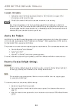
Page 110: ...E Network Camera 1 2 3 4 110 5 6 SD SD SD 1 106 2 STP STP AXIS Windows IP AXIS IP Utility AXIS Camera Management www axis com techsup Internet Explorer Windows Safari OS X ChromeTM Firefox Axis www ax...

Page 111: ...5 30 4 LED DHCP IP 192 168 0 90 5 IP Web Setup Setup Setup System System System Options Options Options Maintenance Maintenance Maintenance www axis com www axis com techsup Setup Setup Setup About Ab...

Page 112: ...Installation Guide Ver M1 3 AXIS Q1775 E Network Camera Date June 2015 Axis Communications AB 2015 Part No 62889...

Reviews: