background image


Installation Manual


Page 16 / 16 


Module application: Class A 
Module Fire Performance: Type 1 or Class C (for CUL) 
Recommended maximum Series/Parallel module configuration: 16/1 for models as 
follows: AC-"XXX"P/72S; AC-"XXX"M/72S; AC-"XXX"P/72X; AC-"XXX"M/72X 
19/1 for models as follows:AC-"XXX"P/60S; AC-"XXX"M/60S; AC-"XXX"P/60X; AC-
"XXX"M/60X 
Maximum series fuse: 20A / Maximum system voltage: 1000V 

7.3     Type: AC-"XXX"MH/144S & AC-"XXX"MH/120S 

(XXX is power rating)  

Standard test condition: 1000W/m

2

, AM1.5, at 25°C


Module application: Class A  
Module Fire Performance: Type 1 or Class C (for CUL) 
Recommended maximum Series/Parallel module configuration: 16/1 for models as 
follows: AC-"XXX"MH/144S 19/1 for models as follows: AC-"XXX"MH/120S  
Maximum series fuse: 20A / Maximum system voltage: 1000V 


7.4


Type: AC-"XXX"MH/144V & AC-"XXX"MH/120V 
(XXX is power rating)  
Standard test condition: 1000W/m

2

, AM1.5, at 25°C 

Module application: Class A  
Module Fire Performance: Type 1 or Class C (for CUL) 
Recommended maximum Series/Parallel module configuration: 24/1 for models as 
follows: AC-"XXX"MH/144V  29/1 for models as follows: AC-"XXX"MH/120V  
Maximum series fuse:20A / Maximum system voltage: 1500V 


8.


Editing records of installing manual  


Version 

Date 

Changing information 

Comments 

US10162018 

2018-10-16 

NA 


US04302019 

2019-04-30 

Half Cut update wattages 

Electrical and wattages added for HC 

US10232019 

2019-10-23 

Half Cut update wattages 

Electrical and wattages added for HC 

US03102020 

2020-03-10 

Half Cut Update Electrical Data 

Summary of Contents for AC-280M/60S

Page 1: ...AXITEC LLC 1819 Underwood Boulevard Suite 5 Delran New Jersey 08075 USA Info axitecsolar com 1 856 393 7800 AXITEC LLC Installation Manual Version Date 03102020 ...

Page 2: ...nd maintenance AXITEC LLC modules will provide you with clean and renewable solar electricity for years to come This manual contains necessary installation maintenance and safety information The word module as used in this manual refers to one or more PV modules Retain this manual for future reference DISCLAIMER OF LIABILITY AXITEC LLC does not assume responsibility and expressly disclaims liabili...

Page 3: ... with tempered glass but still must be handled with care If the front glass is broken or if the polymer back skin is torn contact with any module surface or the frame can produce electrical shock particularly when the module is wet Broken or damaged modules must be disposed of properly 1 5 Axitec LLC modules are intended for use in terrestrial applications only thus excluding aerospace or maritime...

Page 4: ...should not be shaded at any time of the day Do not use module near equipment or in ad loc 3 2 Selecting the proper support frame Always observe the instructions and safety precautions included with the support frame to be used with the module Do not attempt to drill holes in the glass surface of the module Do not drill additional mounting holes in the frame of the module Doing so will void the war...

Page 5: ...fect the fireproofing of the house construction The fire rating of this module is valid only when mounted in the manner specified in the mechanical mounting instructions The modules are rated fire Class C and are suitable for mounting over a class A roof When installing the module on a roof or building do so in calm winds Installing a module during strong winds may cause accidents The System Fire ...

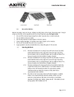
Page 6: ...ing holes located in the frame back flanges See the table as follow The torque should be 12 5N m 18N m to tighten the bolt 3 7 2 Modules installed with mounting holes 10 6 5 Modules should be bolted with M6 bolt to the support structures through mounting holes located in the frame back flanges See the table as follow The torque should be 12 5N m 18N m to tighten the bolt 3 7 3 Modules installed wi...

Page 7: ...box or electrical leads DO NOT stand or step on module DO NOT drop module or allow objects to fall on module DO NOT set the module down hard a surface To avoid glass breakage DO NOT place any heavy objects on the module Inappropriate transport and installation may break the glass of the module ...

Page 8: ...a safety factor is 1 5 High level loading condition Apply to harsher environment conditions such as storm heavy snow etc Rated load is 3600Pa safety factor is 1 5 Mounting system Clamping system At tach to the long frame Permissible range of clamp 0 S 1 4L Permissible range of clamp 1 4L 50 S 1 4L 50 Clamping system At tach to the short frame Permissible range of clamp 0 H 1 4W ...

Page 9: ...Installation Manual Page 8 16 Clamp A use for frame with 40mm height Clamp A use for frame with 35mm height Clamp B ...

Page 10: ...exceed the maximum allowable system voltage as listed on the module label All module frames should be grounded for safety 4 4 Under normal conditions a photovoltaic module may experience conditions that produce more current and or voltage than reported at Standard Test Conditions Accordingly the values of short circuit current and open circuit voltage marked on modules should be multiplied by a fa...

Page 11: ...and evaluated through the requirements in UL 1703 may be used for grounding connections in accordance with the instructions provided with the module All the PV modules frame and installing support must be earthed correctly in accord to local electrical laws use correct ways of grounding using suitable grounding wires to connect PV modules and frame supports Grounding wires materials can be copper ...

Page 12: ... AC XXX M 72V AC XXX M 72S 40 85 1640 1650 992 40 or 1640 1650 992 35 AC XXX M 60V AC XXX M 60S 40 85 1956 1966 992 40 AC XXX P 72XV AC XXX P 72X 40 85 1640 1650 992 40 or 1640 1650 992 35 AC XXX P 60XV AC XXX P 60X 40 85 1956 1966 992 40 AC XXX M 72XV AC XXX M 72X 40 85 1640 1650 992 40 or 1640 1650 992 35 AC XXX M 60XV AC XXX M 60X 40 85 2000 992 40 AC XXX MH 144S AC XXX MH 144V 40 85 1675 992 3...

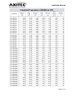
Page 13: ...9 74 300 20 AC 305M 60S 39 81 32 42 1000 9 41 9 83 305 20 AC 310M 60S 39 9 32 47 1000 9 55 9 92 310 20 AC 305MH 120S 39 42 32 38 1000 9 42 9 86 305 20 AC 310MH 120S 39 58 32 58 1000 9 52 9 95 310 20 AC 315MH 120S 39 74 32 79 1000 9 61 10 04 315 20 AC 320MH 120S 39 92 33 01 1000 9 69 10 13 320 20 AC 325MH 120S 40 1 32 71 1000 9 93 10 43 325 20 AC 330MH 120S 40 27 32 91 1000 10 02 10 51 330 20 AC 33...

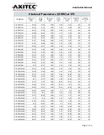
Page 14: ...74 300 20 AC 305M 60V 39 81 32 42 1500 9 41 9 83 305 20 AC 310M 60V 39 9 32 47 1500 9 55 9 92 310 20 AC 305MH 120V 39 42 32 38 1500 9 42 9 86 305 20 AC 310MH 120V 39 58 32 58 1500 9 52 9 95 310 20 AC 315MH 120V 39 74 32 79 1500 9 61 10 04 315 20 AC 320MH 120V 39 92 33 01 1500 9 69 10 13 320 20 AC 325MH 120V 40 1 32 71 1500 9 93 10 43 325 20 AC 330MH 120V 40 27 32 91 1500 10 02 10 51 330 20 AC 335M...

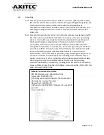
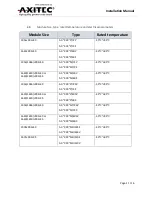
Page 15: ... for Use in Photovoltaic Systems UL 6703 the specific allowable mating connector manufacturer s and model number s are listed as below different model connectors should not be mated with each other Connector model name Allowable mating connector model name PV ZH202 SBN PV ZH202 SBN TL Cable01 TL Cable01 PV JM601 PV JM601 PV ZH202B Series PV ZH202B Series TL CABLE01S FM TL CABLE01S FF PV JM601A PV ...

Page 16: ...ce of the modules 6 7 To keep all of the electrical contacts in good working condition keep modules in a dry and un contaminated area prior to installing 6 8 If temporary storage is needed the storage space should be a dry well ventilated area 7 Module information 7 1 Type AC XXX P 72V AC XXX M 72V AC XXX P 72XV AC XXX M 72XV AC XXX P 60V AC XXX M 60V AC XXX P 60XV AC XXX M 60XV XXX is power ratin...

Page 17: ...els as follows AC XXX MH 144S 19 1 for models as follows AC XXX MH 120S Maximum series fuse 20A Maximum system voltage 1000V 7 4 Type AC XXX MH 144V AC XXX MH 120V XXX is power rating Standard test condition 1000W m2 AM1 5 at 25 C Module application Class A Module Fire Performance Type 1 or Class C for CUL Recommended maximum Series Parallel module configuration 24 1 for models as follows AC XXX M...

Reviews: