V 2 0 0 2 1 3 E N
S e i t e
19 | 27
1.
Remove the safety cover of the "Power" sockets.
2.
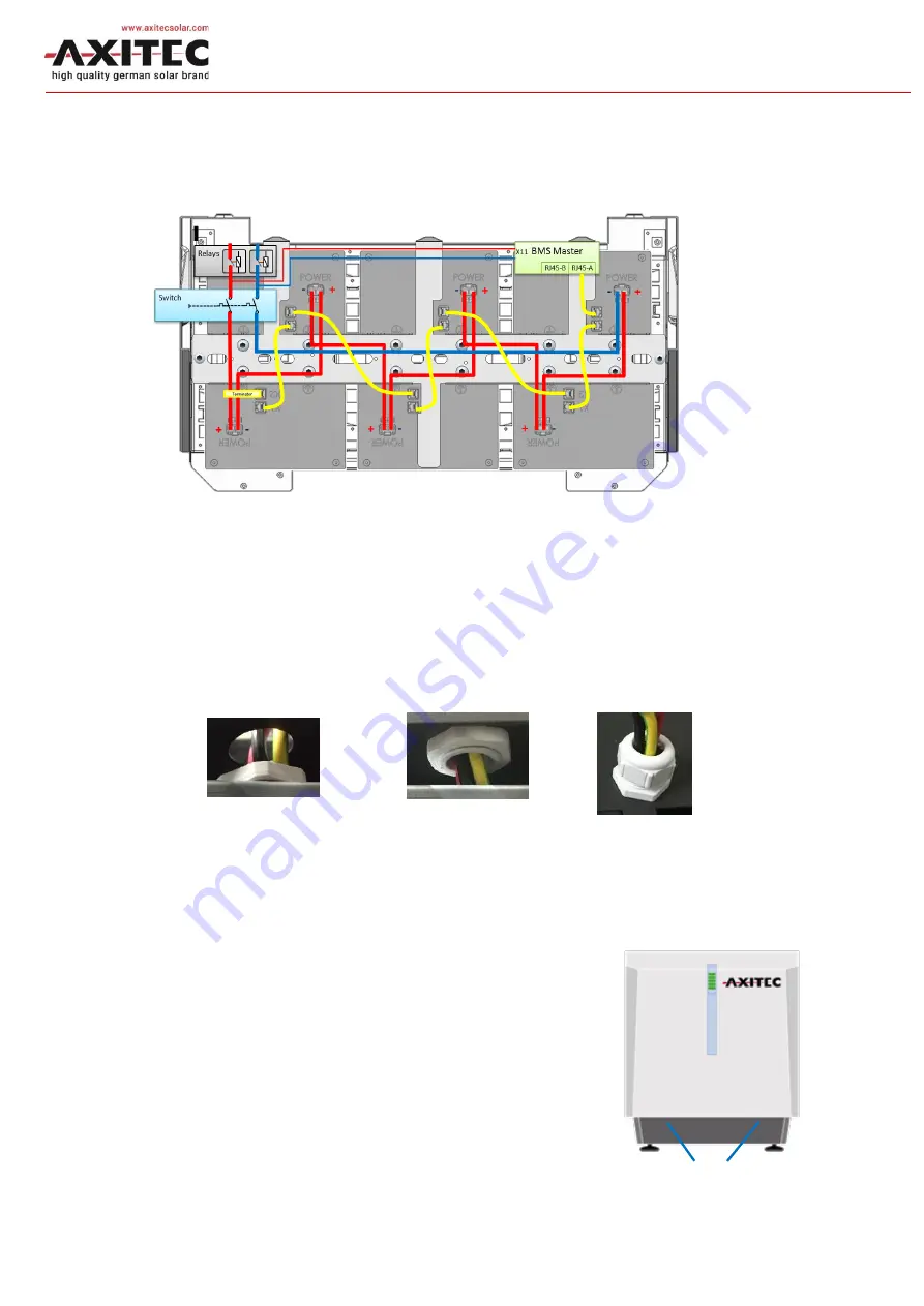
Insert the power plug for the respective Energypack until it clicks into place. For
example, refer to Figure 5.
Figure 5:
Power pa th with s witching devi ces a nd BMS
3.
Check by pulling the power plugs to make sure that the latching is engaged.
4.
If there are less than 6 Energypack: Fit the power plugs not required with the dummy
sockets
D
supplied.
5.
Feed the power cables (red and black) as well as PE (yellow-green) through the left
hole in the basic housing and fix them with the supplied PG screw connection .
6.
Lead the communication cable through the right hole and fix it with the supplied cable
gland.
3.3.3
Closing the housing of the battery system
1.
Position the housing hood (with display) in front of the
housing base and plug the cable for the display on the
board into the hood.
2.
Insert the hood into the guide at the top and close it at
the bottom with the two M5x10 hexagon socket
screws (SW4) which were unscrewed in
Screws M5 (SW4)


