background image

AC305WL 
Woodturning Lathes

Code 105119

Original  Instructions

AT&M: 22/06/2018

BOOK REF : 105170

Summary of Contents for AC305WL

Page 1: ...AC305WL Woodturning Lathes Code 105119 Original Instructions AT M 22 06 2018 BOOK REF 105170 ...

Page 2: ...ficate No AM50361061 AE501701975 has been issued by Laizhou Chunlin Machinery Co Ltd at No 269 Baoshi Road Wenfeng Street Laizhou City Shandong 261400 China and complies with the relevant essential health and safety requirements 2006 42 EC 2006 95 EC 06 42 EC Annex I 05 2006 EN 61029 1 2009 A11 declares that the machinery described This machine complies with the following directives EU Declaration...

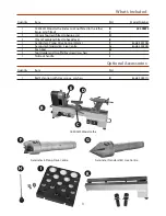
Page 3: ...ted to headstock E 1 Axminster 4 Prong Drive Centre 25mm F code 340106 1 Axminster Standard 60 Live Centre G code 340203 1 Push Rod H 1 Tool Holder and two Phillips screws washers I 1 Tailstock handle J Quantity Item Part 1 Bed Extension with Hex screws washers K code 504511 Axminster 4 Prong Drive Centre Axminster Standard 60 Live Centre AC305WL Wood Lathe Optional Accessories B F G K I H E D C ...

Page 4: ...thing goggles gloves masks etc Wear ear defenders at all times If you have long hair wear a hair net or helmet to prevent it being caught up in the rotating parts of the machine Consideration should be given to the removal of rings and wristwatches Consideration should also be given to non slip footwear etc If another person is to use the machine ensure they are suitably qualified to use it Do not...

Page 5: ...alls coverall et al rubber gloves are also a good idea as is eye protection if your cleaning process tends to be a little bit enthusiastic After cleaning lightly coat the machine with a thin layer of light machine oil N B If you used paraffin kerosene make sure you apply this thin film sooner rather than later 95 of the machine comes fully assembled all that remains is to fit the four prong drive ...

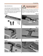
Page 6: ...HE CASTING I Line up the machined slots in the tool holder I and slide the holder down over Phillips screws then lightly tighten the screws to clamp the holder in place see figs 5 6 Tool Holder DON T OVERTIGHTEN THE PHILLIPS SCREWS AS THE HOLDER IS ONLY PLASTIC NOTE There are also two pre drilled holes under the tailstock if you wish to mount the tool holder there Locate the tailstock handle and s...

Page 7: ...over the Hex screws and lightly screw them into the threaded holes see fig 10 Optional Bed Extension Release the tailstock clamping lever and position the tailstock across the join to align both beds re clamp the tailstock in position and tighten both Hex screws see figs 11 12 Both beds are now aligned NOTE DON T TIGHTEN THE SCREWS AT THIS POINT 7 Assembly 7 Fig 07 Fig 08 Fig 10 Fig 09 Fig 11 Fig ...

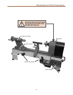
Page 8: ... rest Lathe bed Motor handle Push rod tool holder Motor handle lock Rubber foot 60 Live centre Index lock pin 4 Prong drive centre Tool rest lock Tailstock handle Banjo arm lock ON OFF Variable speed control Motor Lower pulley door lock Speed control dial AC305WL Control box ...

Page 9: ...9 Illustration and Parts Description Tailstock lock Tool holder Power cable hooks Tailstock barrel lock WARNING MAKE SURE THE INDEX LOCK PIN IS IN THE UP POSITION BEFORE SWITCHING ON Headstock ...

Page 10: ...tached giving a maximum of 965mm between centres Fig 13 Indexing assembly facility Fig 15 Motor pulley access door Index pointer Index locking pin Door knob spring lock Fig 14 Tailstock barrel with scale Fig 16 Lower the headstock cover to reveal the pulley system ...

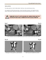
Page 11: ...down position The indexing facility is useful for fluted columns clock faces and accurate hole positioning Lift and Rotate the index locking pin knob to unlock the headstock spindle turn the faceplate and line up one of the positions then lower the indexing pin to lock the spindle in position see figs 17 18 19 20 Indexing Facility WARNING DO NOT USE THE INDEX PIN WHEN REMOVING THE FACEPLATE OR CHU...

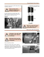
Page 12: ...ging the Lathe Speed DISCONNECT THE LATHE FROM THE MAINS SUPPLY BEFORE CONTINUING 1 Open the motor pulley access door by pulling the door knob back see figs 21 22 Lower the headstock cover to access the pulleys see fig 23 2 Release the motor handle lock and lift the motor up tighten the handle to lock the motor in position this releases the tension on the pulleys see figs 24 25 PLEASE NOTE THE FOL...

Page 13: ...k cover and close the motor access door Pulley grooves NOTE The speed chart above shows approximate speeds with the lathe off load Removing the Faceplate DISCONNECT THE LATHE FROM THE MAINS SUPPLY BEFORE CONTINUING MAKESURE THE LOCKING PIN IS IN THE UP POSITION BEFORE CONTINUING You will require two spanners Place the first spanner onto the lathe spindle a and the other on the faceplate b see fig ...

Page 14: ...r details over the lathe bed to allow the Banjo and Tailstock to run more smoothly over the bed also spray the headstock and tailstock to prevent corrosion Check the tension of the belt and adjust if required See Changing the Belt Speed Also check the condition of the belt for signs of wear and change if required contact our technical department on 03332 406406 Check any build up of wood shaving o...

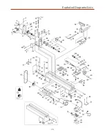
Page 15: ...15 Exploded Diagrams Lists ...

Page 16: ...cover 1 13 Ball bearing 80105 2 57 Pin hinge 1 14 Retaining ring 47 2 58 Mounting plate 1 15 shaft 1 59 Ball 1 16 Cap 1 60 Knock out rod 1 17 Screw 1 61 Hinge 2 18 Bush 1 62 Door latch 1 19 Spring 1 63 Drive belt 1 20 Index pin 1 64 Connecting rod 1 21 Hex socket screw M8 30 4 65 Spring t 1 22 Spring washer 4 66 Washer 1 23 Washer ø8 4 67 The main body 1 24 Nut M10 1 68 Motor pulley 1 25 Indicator...

Page 17: ...ol rack 2 103 Cup center 1 86 Lock nut 2 104 Ball bearing 1 87 Nut M10 1 105 Taper rod 1 88 Rubber washer 6 106 Bed 1 89 Support 1 107 Nut M10 1 90 Semi circle head screw M5 12 4 108 Hex socket screw M8 16 1 91 Washer ø5 2 109 Semi circle head screw M4 20 3 92 Screw 1 110 Cam follower tailstock 1 93 Bush 1 111 Motor pulley 1 94 Quill adjusting wheel 1 114 Extension bed 1 95 Eccentric axis 1 115 Sm...

Page 18: ...Wiring Diagram 18 ...

Page 19: ...19 Notes 19 ...

Page 20: ...s together with household waste material By law they must be collected and recycled separately EU Countries Only The Axminster guarantee is available on Craft Trade Engineer AirTools CNCTechnology Series machines Buy with confidence from Axminster So sure are we of the quality we cover all parts and labour free of charge for three years For more information visit axminster co uk 3years ...

Reviews: