12
Operating Instructions
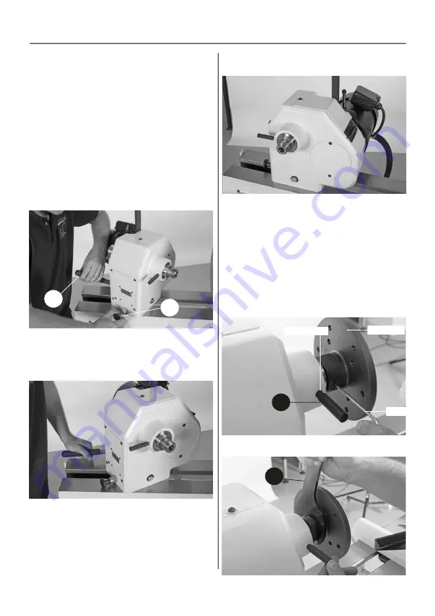
Rotating the Headstock
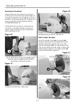
The Headstock can be swivelled in any position
by lifting up the Headstock locking handle (a) and
pulling the Headstock pivot lock (b) out, swivel the
Headstock to the desired position is reached, lock in
place by pushing down the headstock locking
handle (a). (See figure 18)
The Headstock incorporates two index positions
45˚and 90˚, swivel the headstock until it locks in
place to allow bowls to be turned in front of the
lathe. (See figures 19-20)
Figure 18
Lift up the Headstock locking handle (a), pull the
Headstock pivot lock (b) out and swivel the
Headstock to the desired position
Figure 19
The Headstock locked in the 45˚ index position
Figure 20
The Headstock locked in the 90˚ index position
Removing the faceplate
Locate the spindle lock pin (D) and spanner (B).
Rotate the spindle until the machined hole on the
shaft lines up with the spindle collar access hole.
Insert the locking pin (D) to lock the spindle, using
a Hex key loosen the two grub screws on either side
of the spindle, see figure 21. Using the spanner (B)
remove the faceplate, see figure 22.
Figure 21
Figure 22
a
b
D
B
Hex key
Faceplate
Access hole
Summary of Contents for 502703
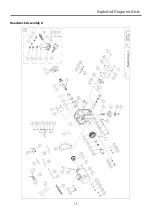
Page 15: ...15 Exploded Diagrams Lists Headstock Assembly A ...
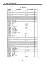
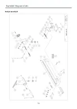
Page 16: ...16 Exploded Diagrams Lists Headstock Assembly A ...
Page 17: ...17 Exploded Diagrams Lists Headstock Assembly A ...
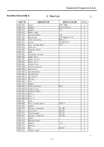
Page 18: ...18 Exploded Diagrams Lists Body Assembly B ...
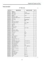
Page 19: ...19 Exploded Diagrams Lists Body Assembly B ...
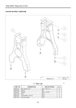
Page 20: ...20 Exploded Diagrams Lists Stand Assembly C Optional ...
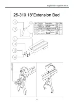
Page 21: ...21 Exploded Diagrams Lists ...
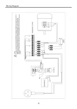
Page 22: ...22 Wiring Diagram ...
Page 23: ...23 Notes ...


