Setting the Fence
21
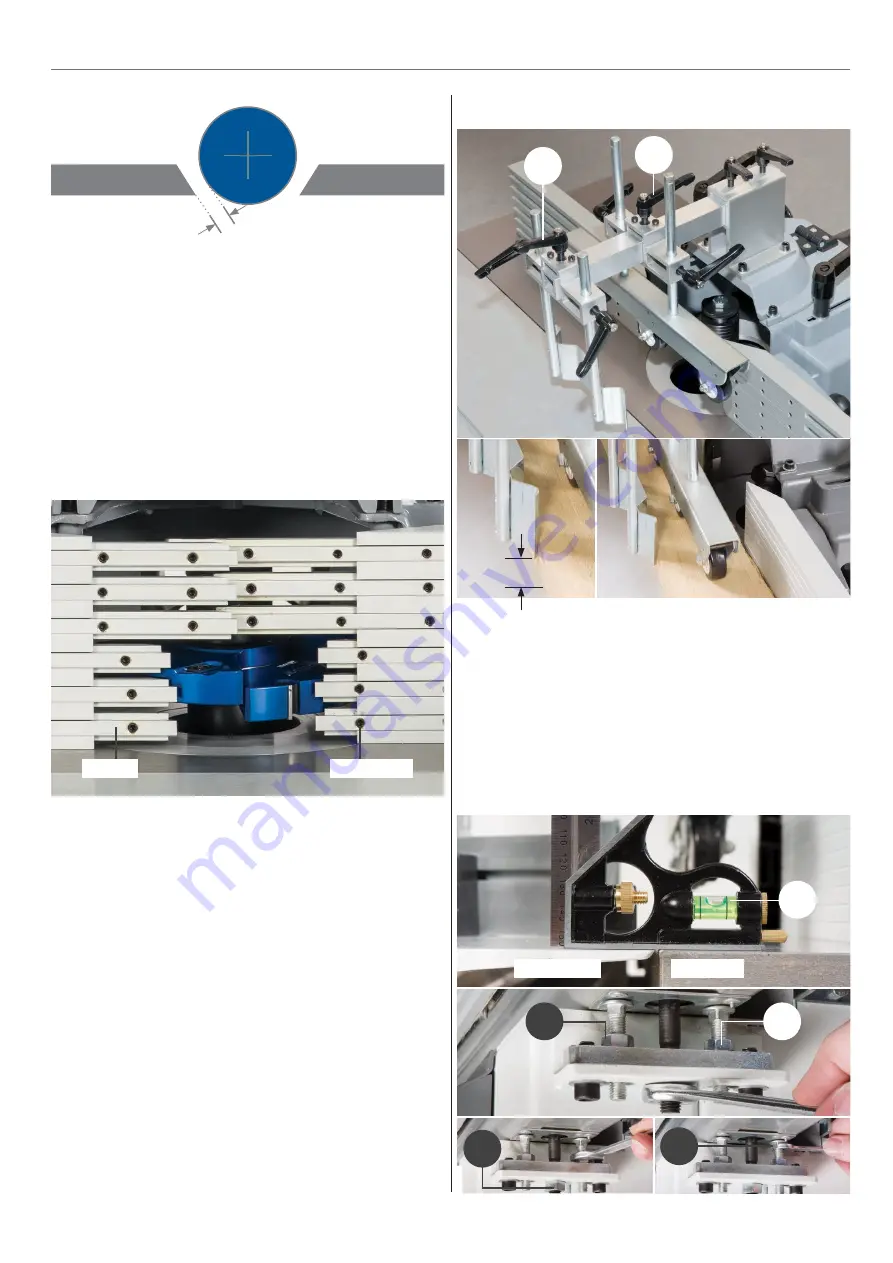
Adjust the position of the fence assembly to give both the
required cutter protrusion and adequate clearance between
the cutter and the fence. Close up the aluminium fences to
give approximately 5mm clearance around the cutter, see
diagram above.
NOTE: Built into the fence assembly are adjustable fingers to
accurately set the clearance around the cutter. To adjust the
fingers loosen the grub screws, see fig 48. Retighten when
complete.
Fig 48
5mm
Grub screw
Fingers
The fence is used to guide small work pieces through the cutter
without them being trapped between the fence and the cutter.
The dust extraction hose is connected to the aperture at the
rear of the fence assembly.
Before starting work, carefully check that the cutter can rotate
freely without fouling the inside of the guard and that the
guard is clamped firmly in place.
Adjusting the Feeder Roller & Ant-Kickback Assembly
Levelling the Sliding Table
Loosen the feeder roller clamp handle (a) and move the feeder
roller to the centre of the work piece, retighten the handle.
Undo the anti-kickback clamp handle (b) and move the assem-
bly near the work piece, retighten the handle. Raise the anti-
kickback assembly so the steel plate is about 5-10mm above
the work table, see figs 49-50.
Fig 49-50
a
b
5-10mm
Place a level between the sliding table and work table, check
that both tables are level. If adjustment is required loosen the
three nuts (c) beneath the sliding table and adjust the two
coach bolts (d), until the bubble on the level is between the
two markers (e), tighten the three nuts (e), see fig 51-52.
Fig 51-52
Sliding table
Work table
c
c
d
e
c
Note: The tables are preset at the factory but can be adjusted.
Continues Over...
Fence
Fence
Cutter block


