Setting up the Machine
21
Correctly setting the tables and the cutter block is important,
not only to improve the quality of the work, but also to the
safety when operating the machine.
Surface Tables and Cutter Block
Setting the Fence at 90˚
Setting the Fence at 45˚
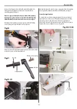
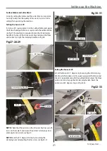
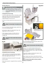
1. Using a 90˚ square, place it on the outfeed table and against
the fence, checking the fence is square with the outfeed table,
see fig 27. If adjustment is required loosen the tilt clamping
handle to the rear of the fence assembly and adjust the fence
until correct, re-tight the clamping handle, see fig 28.
Fig 27-28-29
NOTE: Check that the pointer on the tilt assembly lines up with
‘zero’ on the scale. If, not loosen the pointer’s clamping screw
and adjust until correct, see fig 29.
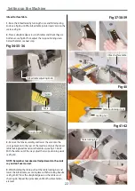
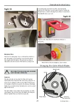
NOTE: Reset the 90˚ degree tilt stop by loosening the
clamping nut and adjusting the Hex screw, see fig 30-31.
Tilt clamping handle
90˚ Square
Scale
Pointer
Fig 30-31
Hex screws
Clamping nut
90˚ tilt stop
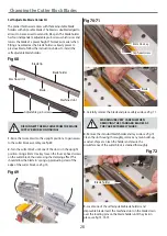
2. Set the fence to 45˚ degrees by loosening the tilt clamping
handle as before, place a mitre square up against the fence and
check it’s perpendicular with the outfeed table. Adjust the fence
until correct and nip up the tilt clamping handle. Reset the
pointer and 45˚ degree stop, see fig 32-33.
Fig 32-33
Mitre square
Outfeed table
45˚ tilt stop
Continues Over....
Summary of Contents for AT260PT
Page 4: ...What s Included 4 C D F E G H I ...
Page 5: ...What s Included 5 L N K J M Continues Over ...
Page 34: ...Exploded Diagrams Lists 34 DIAGRAM A AT260PT AT260SPT PlanerThicknesser ...
Page 36: ...Exploded Diagrams Lists 36 AT260PT AT260SPT PlanerThicknesser DIAGRAM B ...
Page 38: ...Exploded Diagrams Lists 38 AT260PT AT260SPT PlanerThicknesser DIAGRAM C ...
Page 40: ...Exploded Diagrams Lists 40 AT260PT AT260SPT PlanerThicknesser DIAGRAM D ...
Page 42: ...Exploded Diagrams Lists 42 AT260PT AT260SPT PlanerThicknesser DIAGRAM E ...
Page 46: ...Exploded Diagrams Lists 46 DIAGRAM A AT310SPT PlanerThicknesser ...
Page 48: ...Exploded Diagrams Lists 48 DIAGRAM B AT310SPT PlanerThicknesser ...
Page 50: ...Exploded Diagrams Lists 50 DIAGRAM C AT310SPT PlanerThicknesser ...
Page 52: ...Exploded Diagrams Lists 52 DIAGRAM D AT310SPT PlanerThicknesser ...
Page 54: ...Exploded Diagrams Lists 54 DIAGRAM E AT310SPT PlanerThicknesser ...
Page 58: ...Spiral Cutter Block Diagram 58 Spiral Cutter Block 10 Inch Spiral Cutter Block 12 Inch ...
Page 59: ...Wiring Diagrams 59 AT260PT AT260SPT DIAGRAM AT310SPT DIAGRAM ...

