Setting up the Machine
23
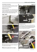
Thicknessing Table
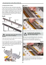
1. Raise the surface tables as explained on the opposite page.
2. Release the rise and fall clamping handle (A) and turn
the operating wheel (B) counterclockwise to lower the
thicknessing table until the pointer reads 190 on the
scale and check the stop is up against the underside of the
thicknessing table. If not, loosen the locking nut and adjust
the stop then re-tighten the nut to lock the setting, see fig
43-44-45-46.
Fig 43-44-45-46
B
A
Pointer
Scale
Table stop
Locking nut
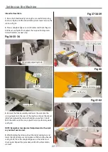
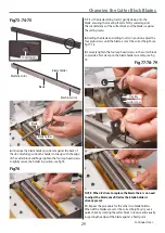
Table Extension
Fig 47
1. Place a straight edge across the thicknessing table and guide
roller and check they are both in line with each other, see fig 47.
2. If adjustment is required, loosen the two cap head bolts (A)
and adjust the Hex bolts (B) until alignment is reached, tighten
the nuts (C) to lock the setting. Re-tighten the cap head bolts
(A), see fig 48.
Fig 48
Straight edge
Table extension
Guide roller
A
B
C
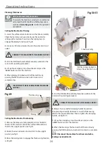
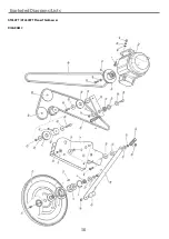
Ascertain the orientation of the machine and move it to its
desired position in the workshop. Ensure that the machine is
positioned to allow sufficient clearance all round to cater for
the maximum length of timber you wish to machine. The
machine should be positioned on a flat level surface.
Positioning the Machine
Allow sufficient
clearance all round
the machine
Table stop
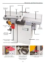
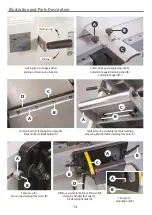
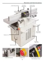
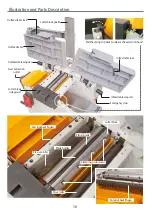
Summary of Contents for AT260PT
Page 4: ...What s Included 4 C D F E G H I ...
Page 5: ...What s Included 5 L N K J M Continues Over ...
Page 34: ...Exploded Diagrams Lists 34 DIAGRAM A AT260PT AT260SPT PlanerThicknesser ...
Page 36: ...Exploded Diagrams Lists 36 AT260PT AT260SPT PlanerThicknesser DIAGRAM B ...
Page 38: ...Exploded Diagrams Lists 38 AT260PT AT260SPT PlanerThicknesser DIAGRAM C ...
Page 40: ...Exploded Diagrams Lists 40 AT260PT AT260SPT PlanerThicknesser DIAGRAM D ...
Page 42: ...Exploded Diagrams Lists 42 AT260PT AT260SPT PlanerThicknesser DIAGRAM E ...
Page 46: ...Exploded Diagrams Lists 46 DIAGRAM A AT310SPT PlanerThicknesser ...
Page 48: ...Exploded Diagrams Lists 48 DIAGRAM B AT310SPT PlanerThicknesser ...
Page 50: ...Exploded Diagrams Lists 50 DIAGRAM C AT310SPT PlanerThicknesser ...
Page 52: ...Exploded Diagrams Lists 52 DIAGRAM D AT310SPT PlanerThicknesser ...
Page 54: ...Exploded Diagrams Lists 54 DIAGRAM E AT310SPT PlanerThicknesser ...
Page 58: ...Spiral Cutter Block Diagram 58 Spiral Cutter Block 10 Inch Spiral Cutter Block 12 Inch ...
Page 59: ...Wiring Diagrams 59 AT260PT AT260SPT DIAGRAM AT310SPT DIAGRAM ...

