Operating Instructions
24
Planning/ Thicknesser
HSE Health and Safety Executive
To operate the machine correctly, it is recommend-
ed to read the HSE (Health and Safety Executive)
website at www.hse.gov.uk. on the safe operation
procedures.
Setting the Machine for Planing
Setting the Machine for Thicknessing
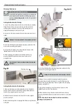
1. Lower the surface tables and re-mount the fence assembly.
Check the machine is set up correctly, see the section for
setting up the machine. Press down the locking lever to
engage the planing function, see fig 49.
2. Connect a 100mm extraction hose to the extraction hood
outlet.
Fig 49
Thicknessing
Planing
CONNECT THE MACHINE TO THE MAINS SUPPLY!
CONNECT THE MACHINE TO THE MAINS SUPPLY!
DISCONNECT THE MACHINE FROM THE MAINS
SUPPLY!
3. Visit the HSE (Health and Safety Executive) website for the
correct safe operating procedures.
4. Lift up the emergency stop shroud lever and press the
‘GREEN’ button to start the machine.
5. When planing is finished switch off the machine by
pressing the ‘RED’ button and wait until it comes to a
complete stop.
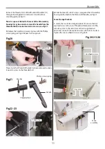
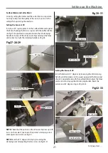
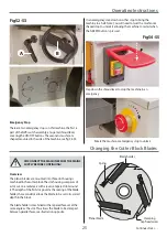
1. Remove the fence assembly and place it in its holder to
the rear of the machine. Unlock the surface table and raise
them to the upright position, see fig 50.
2. Rotate the dust extraction hood until it’s in the upright
position, see fig 51.
3. Raise the locking lever to engage the thicknessing function,
see fig 49.
Fig 50-51
5. Visit the HSE (Health and Safety Executive) website for the
correct safe operating procedures.
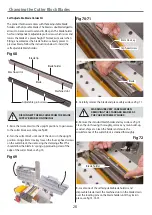
6. Release the rise and fall clamping handle (A) and turn
the operating wheel (B) clockwise to raise the thicknessing
table to the required thickness then re-tighten the clamping
handle, see fig 52-53.
7. Lift up the emergency stop shroud lever and press the
‘GREEN’ button to start the machine.
8. When thicknessing is finished switch off the machine by
pressing the ‘RED’ button and wait until it comes to a complete
stop.
NOTE: Disconnect the machine from the mains before
making any adjustments.
Fence assembly
Pull the spring clip back to
release the extraction hood
Summary of Contents for AT260PT
Page 4: ...What s Included 4 C D F E G H I ...
Page 5: ...What s Included 5 L N K J M Continues Over ...
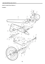
Page 34: ...Exploded Diagrams Lists 34 DIAGRAM A AT260PT AT260SPT PlanerThicknesser ...
Page 36: ...Exploded Diagrams Lists 36 AT260PT AT260SPT PlanerThicknesser DIAGRAM B ...
Page 38: ...Exploded Diagrams Lists 38 AT260PT AT260SPT PlanerThicknesser DIAGRAM C ...
Page 40: ...Exploded Diagrams Lists 40 AT260PT AT260SPT PlanerThicknesser DIAGRAM D ...
Page 42: ...Exploded Diagrams Lists 42 AT260PT AT260SPT PlanerThicknesser DIAGRAM E ...
Page 46: ...Exploded Diagrams Lists 46 DIAGRAM A AT310SPT PlanerThicknesser ...
Page 48: ...Exploded Diagrams Lists 48 DIAGRAM B AT310SPT PlanerThicknesser ...
Page 50: ...Exploded Diagrams Lists 50 DIAGRAM C AT310SPT PlanerThicknesser ...
Page 52: ...Exploded Diagrams Lists 52 DIAGRAM D AT310SPT PlanerThicknesser ...
Page 54: ...Exploded Diagrams Lists 54 DIAGRAM E AT310SPT PlanerThicknesser ...
Page 58: ...Spiral Cutter Block Diagram 58 Spiral Cutter Block 10 Inch Spiral Cutter Block 12 Inch ...
Page 59: ...Wiring Diagrams 59 AT260PT AT260SPT DIAGRAM AT310SPT DIAGRAM ...

