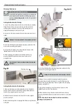
Operating Instructions
25
DISCONNECT THE MACHINE FROM THE MAINS
SUPPLY BEFORE CONTINUING!
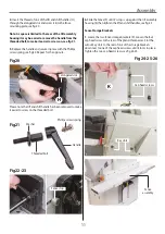
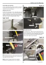
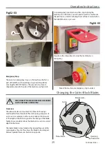
Fig 52-53
A
B
Emergency Stop
There are two emergency stops on this machine, the first is
part of the NVR switch assembly, a large red shroud lever
covering the ON/OFF buttons. The second is mushroom
shaped, mounted to the side of the machine, see fig 54-55.
Fig 54-55
Slap down the shroud lever to stop the machine in an
emergency.
Rotate the mushroom emergency stop to unlock
In an emergency, slap down on either stop to bring the
machine to a halt. Note: You will need to twist the mushroom
shaped stop to unlock it allowing the machine to restart when
the ‘GREEN’ button is pressed.
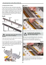
Changing the Cutter Block Blades
Overview
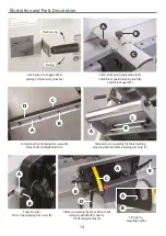
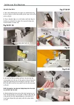
The planer blades are mounted into three slot housings
machined in the cutter block. The slot housing comprises of
a slot cut on a radial axis with a reverse tapered slot around
it. The depth of the first slot governs the seating of the blade
holder, the second slot allows the blade to be set to its correct
depth in the block.
The blade holder is machined with a tapered face set at the
same angle as the slot. This allows the blade to be clamped
between parallel faces, see illustration opposite.
Planer blade
Clamping
Cap head screw
Blade holder
Spring
Continues Over....
Summary of Contents for AT260PT
Page 4: ...What s Included 4 C D F E G H I ...
Page 5: ...What s Included 5 L N K J M Continues Over ...
Page 34: ...Exploded Diagrams Lists 34 DIAGRAM A AT260PT AT260SPT PlanerThicknesser ...
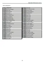
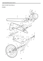
Page 36: ...Exploded Diagrams Lists 36 AT260PT AT260SPT PlanerThicknesser DIAGRAM B ...
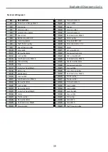
Page 38: ...Exploded Diagrams Lists 38 AT260PT AT260SPT PlanerThicknesser DIAGRAM C ...
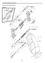
Page 40: ...Exploded Diagrams Lists 40 AT260PT AT260SPT PlanerThicknesser DIAGRAM D ...
Page 42: ...Exploded Diagrams Lists 42 AT260PT AT260SPT PlanerThicknesser DIAGRAM E ...
Page 46: ...Exploded Diagrams Lists 46 DIAGRAM A AT310SPT PlanerThicknesser ...
Page 48: ...Exploded Diagrams Lists 48 DIAGRAM B AT310SPT PlanerThicknesser ...
Page 50: ...Exploded Diagrams Lists 50 DIAGRAM C AT310SPT PlanerThicknesser ...
Page 52: ...Exploded Diagrams Lists 52 DIAGRAM D AT310SPT PlanerThicknesser ...
Page 54: ...Exploded Diagrams Lists 54 DIAGRAM E AT310SPT PlanerThicknesser ...
Page 58: ...Spiral Cutter Block Diagram 58 Spiral Cutter Block 10 Inch Spiral Cutter Block 12 Inch ...
Page 59: ...Wiring Diagrams 59 AT260PT AT260SPT DIAGRAM AT310SPT DIAGRAM ...

