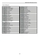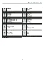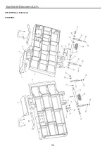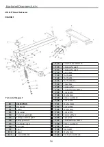
Exploded Diagrams/Lists
44
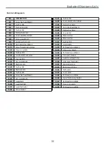
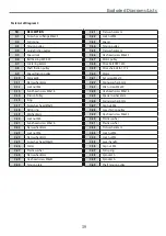
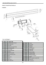
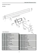
Parts List of Diagram F
NO.
DESCRIPTION
F-1
Left hand cover for fence
F-2
Pan head screw
F-3
Rip fence
F-4
Right hand cover for fence
F-5
Connection plate
F-6
Fence plate
F-7
Adjusting handle
F-8
Washer
F-9
Adjusting handle
F-10
Insert board for fence
F-11
Nut
F-12
Set screw
F-13
Scale
F-14
Set screw
F-15
Pan head screw
F-16
Pointer
F-17
Fence block
F-18
Allen bolt
F-19
Allen bolt
F-20
Left fixing plate
F-21
Sliding plate
F-22
Allen screw
F-23
Clamping plate
F-24
Adjusting handle
F-25
Right fixing plate
F-26
Locking screw M6x12
F-27
Nut M6
F-28
Cross sunk head screew M6x12
F-29
Stop spacer
F-30
Locking plate
AT260PT / AT260SPT Planer Thicknesser
DIAGRAM F
Summary of Contents for AT260PT
Page 4: ...What s Included 4 C D F E G H I ...
Page 5: ...What s Included 5 L N K J M Continues Over ...
Page 34: ...Exploded Diagrams Lists 34 DIAGRAM A AT260PT AT260SPT PlanerThicknesser ...
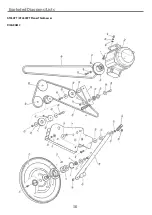
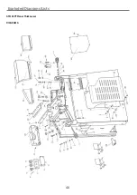
Page 36: ...Exploded Diagrams Lists 36 AT260PT AT260SPT PlanerThicknesser DIAGRAM B ...
Page 38: ...Exploded Diagrams Lists 38 AT260PT AT260SPT PlanerThicknesser DIAGRAM C ...
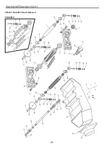
Page 40: ...Exploded Diagrams Lists 40 AT260PT AT260SPT PlanerThicknesser DIAGRAM D ...
Page 42: ...Exploded Diagrams Lists 42 AT260PT AT260SPT PlanerThicknesser DIAGRAM E ...
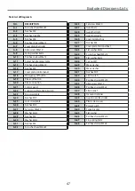
Page 46: ...Exploded Diagrams Lists 46 DIAGRAM A AT310SPT PlanerThicknesser ...
Page 48: ...Exploded Diagrams Lists 48 DIAGRAM B AT310SPT PlanerThicknesser ...
Page 50: ...Exploded Diagrams Lists 50 DIAGRAM C AT310SPT PlanerThicknesser ...
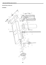
Page 52: ...Exploded Diagrams Lists 52 DIAGRAM D AT310SPT PlanerThicknesser ...
Page 54: ...Exploded Diagrams Lists 54 DIAGRAM E AT310SPT PlanerThicknesser ...
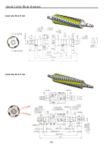
Page 58: ...Spiral Cutter Block Diagram 58 Spiral Cutter Block 10 Inch Spiral Cutter Block 12 Inch ...
Page 59: ...Wiring Diagrams 59 AT260PT AT260SPT DIAGRAM AT310SPT DIAGRAM ...


