Assembly
9
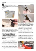
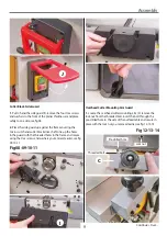
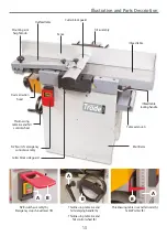
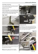
Overhead Cutter Mounting Arm Guard
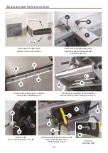
1. Locate the overhead cutter mounting arm (C) remove the
lock nut from the threaded bolt, insert the bolt through the
pre-drilled hole to the side of the outfeed table and secure in
place with the lock nut you removed earlier, see fig 12-13-14.
Fig 12-13-14
Cutter Block Side Guard
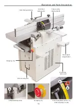
1. Put to hand the side guard (I), remove the four Hex screws
and washers to the front of the planer thicknesser and place
safely to one side, see fig 08.
2. Place the side guard up against the frame covering the
micro switch and cutter block drive shaft. Line up the holes
in the guard with the threaded holes in the frame and secure
using the Hex screws and washers you removed earlier, see fig
09-10-11.
Fig 08-09-10-11
I
C
Lock nut
Threaded bolt
Pre-drilled hole
J
Continues Over....
Summary of Contents for AT260PT
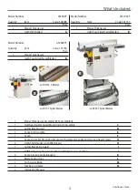
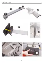
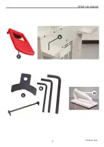
Page 4: ...What s Included 4 C D F E G H I ...
Page 5: ...What s Included 5 L N K J M Continues Over ...
Page 34: ...Exploded Diagrams Lists 34 DIAGRAM A AT260PT AT260SPT PlanerThicknesser ...
Page 36: ...Exploded Diagrams Lists 36 AT260PT AT260SPT PlanerThicknesser DIAGRAM B ...
Page 38: ...Exploded Diagrams Lists 38 AT260PT AT260SPT PlanerThicknesser DIAGRAM C ...
Page 40: ...Exploded Diagrams Lists 40 AT260PT AT260SPT PlanerThicknesser DIAGRAM D ...
Page 42: ...Exploded Diagrams Lists 42 AT260PT AT260SPT PlanerThicknesser DIAGRAM E ...
Page 46: ...Exploded Diagrams Lists 46 DIAGRAM A AT310SPT PlanerThicknesser ...
Page 48: ...Exploded Diagrams Lists 48 DIAGRAM B AT310SPT PlanerThicknesser ...
Page 50: ...Exploded Diagrams Lists 50 DIAGRAM C AT310SPT PlanerThicknesser ...
Page 52: ...Exploded Diagrams Lists 52 DIAGRAM D AT310SPT PlanerThicknesser ...
Page 54: ...Exploded Diagrams Lists 54 DIAGRAM E AT310SPT PlanerThicknesser ...
Page 58: ...Spiral Cutter Block Diagram 58 Spiral Cutter Block 10 Inch Spiral Cutter Block 12 Inch ...
Page 59: ...Wiring Diagrams 59 AT260PT AT260SPT DIAGRAM AT310SPT DIAGRAM ...

