CHANGING THE SANDING DISC
11
DISCONNECT THE SANDER FROM
THE MAINS SUPPLY BEFORE
CONTINUING!
RECONNECT THE SANDER TO THE
MAINS SUPPLY AND CONTINUE
WITH OPERATION.
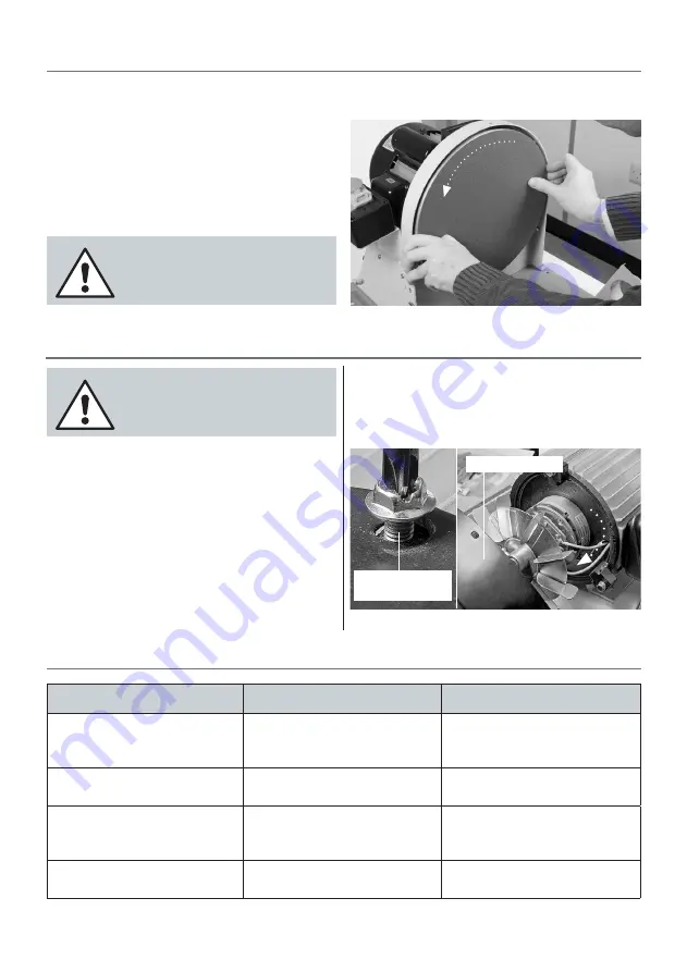
Fig 16
clean dry cloth. Locate the sanding disc, peel the cover from
the adhesive surface and apply
CAREFULLY
to the disc (see
fig 16). Use a piece of cloth in your hand or wear a glove, to
firmly press the abrasive to the disc, the application will be
reinforced by a gentle sanding action across the face when
you first use the new sanding disc.
Step 7
Re-assemble the sander as described opposite but in
reverse (see figs 10 to 14).
MAINTENANCE
There is very little mechanical maintenance that can be
carried out on the machine. Most prudent maintenance
is preventative and concerned with keeping the machine
clean.
1.
At reasonable intervals, inspect and remove all dust/resin
build ups, and blow the motor clean.
2.
Remove the table assembly and lower the extraction
housing, clean any dust or resin build up. Re-assemble the
sander.
3.
Inspect the sanding disc for signs of wear and tear and
replace if necessarily.
4.
From time to time using a damp cloth wipe over the
sanders surface.
TROUBLESHOOTING
TROUBLE
PROBABLE CAUSE
REMEDY
Motor does not run when power
switch is pressed “ON”
1. Switch is burnt out
2. Connection wire is loose or
damaged
1. Replace the switch
2. Tighten wire or replace
Motor does not run at full speed
1. Power voltage is too low
2. Motor is damaged.
1. Test voltage
2. Check and repair motor
Motor does not reach full power
1. Incorrect power wiring
2. Overloaded
1. Replace with the correct size of
power wiring
2. Reduce load
Motor overheating
1. Motor voltage is different
2. Motor is damaged
1. Check the voltage label
2. Check and repair the motor
Turn the disc while applying pressure
Remove the rear guard and blow the motor clean
Remove the three
Phillips screws
Motor rear guard
Summary of Contents for 107627
Page 12: ...EXPLODED DIAGRAMS LISTS 12 Model DS12DL AP305DS ...
Page 14: ...EXPLODED DIAGRAMS LISTS 14 Model DS12DLMB2 AP305BDS ...
Page 16: ...WIRING DIAGRAM 16 ...
Page 17: ...NOTES 17 ...
Page 18: ...NOTES 18 ...
Page 19: ...NOTES 19 ...


