MAIN ASSEMBLY
13
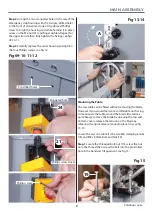
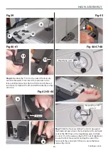
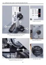
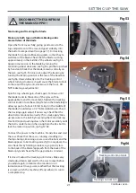
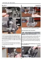
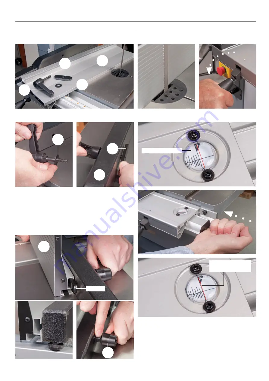
Step 7 Slide the fence assembly (7) until it’s up against
the blade and press down the locking lever (9), see fig 45.
Look at the ‘RED’ line on the magnifying glass to check
it’s set to ‘0’ on the scale, see fig 46. If it’s out of alignment,
loosen the front fence rail (4) and tap the side of the
fence until the scale reads ‘0’ then re-secure the fence
rail, see figs 47-48.
Fig 45
Fig 46-47-48
Magnifying scale
Magnifying scale
set to ‘0’
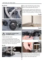
Fig 39
6
10
13
8
Fig 40-41
7
13
10
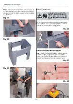
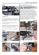
Step 6 Introduce the ‘T’ slot to the side of the fence (6)
over the threaded ‘T’ slot insert (10) and slide on the
fence until the fence (6) is flush with the end of the cast
iron fence (7). Tighten the lift and shift handle (8), see figs
42-43-44.
Fig 42-43-44
Continues over....
‘T’ slot
6
8
Summary of Contents for 107659
Page 1: ...AP2552B Bandsaw Code 107659 AT 12 05 2022 BOOK VERSION 07 ...
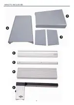
Page 4: ...4 5 6 7 WHAT S INCLUDED 4 2 2 3 ...
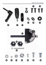
Page 5: ...WHAT S INCLUDED 5 10 9 8 15 14 13 12 11 16 17 18 19 20 21 22 23 24 25 26 ...
Page 29: ...EXPLODED DIAGRAMS LISTS 29 Continues over Main Saw Assembly ...
Page 35: ...WIRING DIAGRAM 35 ...


