MAIN ASSEMBLY
9
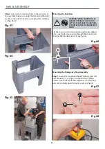
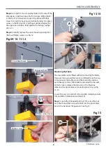
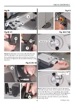
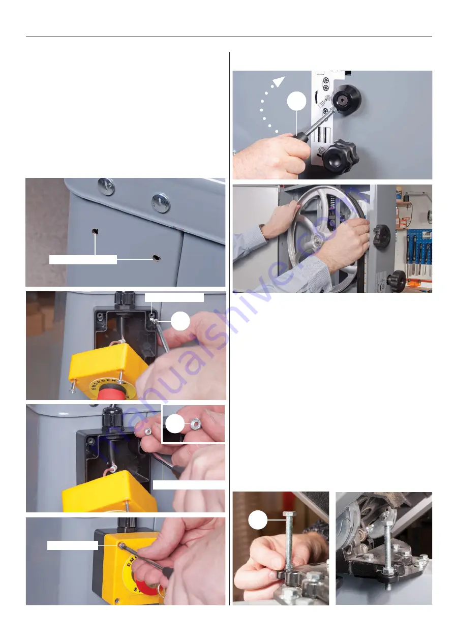
Step 2 Line up the two elongated holes in the rear of the
emergency stop housing with the two pre-drilled holes
to the front of stand, insert one of the domed Phillips
screw through the housing and while holding it in place
screw on the M4 nut (21) and finger tighten. Repeat for
the opposite side then fully tighten the fixings, see figs
09-10-11.
Step 3 Carefully replace the outer housing and tighten
the four Phillips screws, see fig 12.
21
Phillips screw driver
24
Elongated hole
Phillips screw
Fig 09-10-11-12
Pre-drilled holes
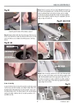
Mounting the Table
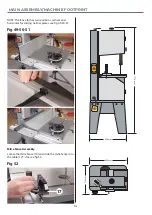
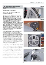
The saw table can be fitted without removing the blade.
However, if you would feel more comfortable not having
to manoeuvre the table around the blade (the table is
quite heavy), remove the blade by opening the top and
bottom covers, release the tension on the blade by
releasing the Quick release tensioning lever (A), see fig
13-14.
Fig 13-14
A
Locate the cast iron table (1) the two M8, clamping knobs
(18) and M8 x 80mm Bolt and Nut (19).
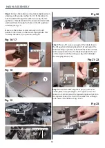
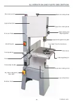
Step 1 Locate the threaded bolt/nut (19), screw the nut
onto the thread then screw the bolt into the pre-drilled
hole in the bandsaw tilt quadrant, see fig 15.
Fig 15
19
Continues over....
Summary of Contents for 107659
Page 1: ...AP2552B Bandsaw Code 107659 AT 12 05 2022 BOOK VERSION 07 ...
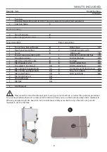
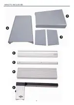
Page 4: ...4 5 6 7 WHAT S INCLUDED 4 2 2 3 ...
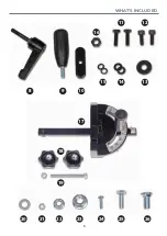
Page 5: ...WHAT S INCLUDED 5 10 9 8 15 14 13 12 11 16 17 18 19 20 21 22 23 24 25 26 ...
Page 29: ...EXPLODED DIAGRAMS LISTS 29 Continues over Main Saw Assembly ...
Page 35: ...WIRING DIAGRAM 35 ...


