6
Assembly
Rubber Feet and Sanding Belt Table
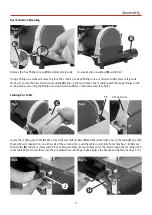
Locate the four rubber feet (F); turn the belt and disc sander (A) on it’s side and insert a rubber foot into each of the four
pre-drilled holes in the base plate (See fig 1). Stand the sander upright.
Locate the sanding belt table (D), M8 x 20mm lift and shift handle (G) and M8 washer (I). The sanding belt table (D)
has a machined cutout slot; slide the belt into the slot until the clamping bracket is flush against the frame. Line up the
machined slot in the bracket with the pre-drilled tappered hole in the casting, using the M8 washer (I) and M8 x 20mm
lift and shift handle (G). Clamp the table in position (See figs 2-3 and 4).
NOTE: You my find it easier if you remove the lift and shift handle (G) and screw the clamping rod in finger tight, then
replace the handle (See fig 3)
NOTE: When tilting the table, it should be adjusted so that the gap between the belt and the table is no larger
than 1.5mm (1/16”). A gap greater than this could cause small workpieces to slip down between the belt and
table.
Lightly screw the clamping rod in until it is finger tight
Tighten the lift and shift handle to clamp the table (D) in
position
Insert the rubber foot into the pre-drilled hole in the base
plate
Lower the sanding belt table (D) in position
Fig 1.
Fig 3.
Fig 2.
Fig 4.
F
G
D
I


