SET UP AND ADJUSTMENT
22
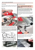
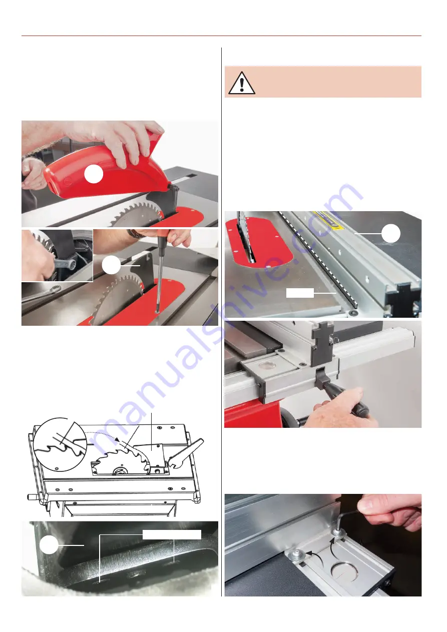
The Riving Knife
1. Raise the saw blade to its highest point and remove the saw
blade crown guard (K) and the table insert, place safely aside,
see fig 71-72.
Fig 71-72
2. Using the spanner loosen the riving knife (H) and check that
the tip of the knife has a clearance of 3-8mm between the
blade. Adjust the four grub screws to the opposite side of the
clamping plate to align the riving knife with the blade. Tighten
the nuts to secure the riving knife in place. NOTE: Check that
the riving knife is parallel to the saw blade by placing the
fence up against them, see fig 73-74.
Fig 73-74
3-8mm
Riving knife (H)
K
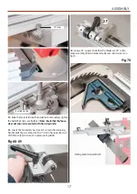
Setting the Rip Fence & Scale
MAKESURE THE BLADE IS SQUARE TO THE
TABLE AND THE FENCE IS SQUARE TO THE
BLADE!
1. Remove the crown guard (K) and rip fence extension (F) and
‘T’ bolts and place safely aside. Line up the fence (E) with the
edge of the tables ’T’ slot and press down the locking handle,
see fig 75-76.
2. Check the fence is parallel with the ‘T’ slot, if adjustment is
required loosen the four Hex screws on either side of the fence
assembly and adjust the fence until it’s in line, see fig 77,
re-tighten the Hex screws.
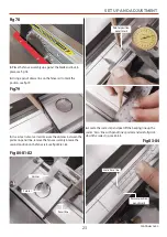
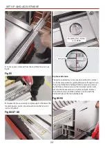
The fence scale does not come pre-mounted to the fence
rail and needs to be stuck in place. NOTE: Before sticking
the scale down make sure the table and fence assembly is
square to the blade. Follow the instruction below.
Fig 75-76
Fig 77
‘T’ Slot
E
Grub screws
H
H
Summary of Contents for 107712
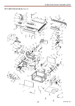
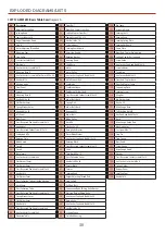
Page 29: ...EXPLODED DIAGRAMS LISTS 29 107712 AW216TS BasicTable Saw Diagram A Continues over ...
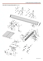
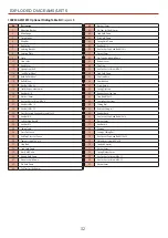
Page 31: ...EXPLODED DIAGRAMS LISTS 31 104930 AW216TS Optional SlidingTable Kit Diagram B Continues over ...
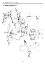
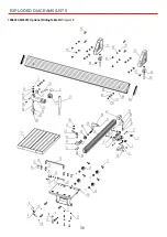
Page 34: ...EXPLODED DIAGRAMS LISTS 34 107713 AW254TS BasicTable Saw Diagram A ...
Page 36: ...EXPLODED DIAGRAMS LISTS 36 106805 AW254TS Optional SlidingTable Kit Diagram B ...
Page 39: ...WIRING DIAGRAM 39 ...


