Assembly
10
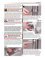
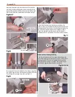
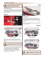
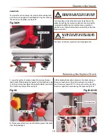
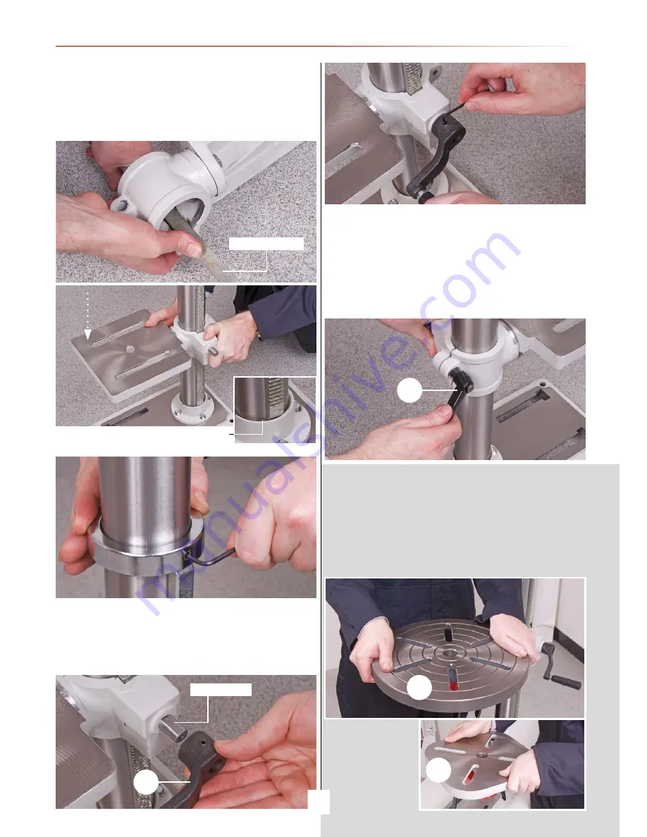
collar over the column and slide it down onto the top of the
rack. Lock it in place with the grub screw, ensuring that it has
captured the upper end of the rack securely, but not too tight
that the rack cannot be swivelled around the pillar see fig 8 .
Fig 06-07
Fig 08
5. Locate and fit the crank handle (9) to the shaft, ensuring that
you tighten the grub screw onto the machined flat on the shaft,
this will keep the worm gear in position, see figs 9-10.
Fig 09
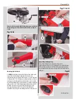
6. Check that the bracket can be driven up and down the
column and can swivel around the pillar. Locate the lift and shift
clamping handle (10) and screw it into the threaded hole to the
rear of the mounting bracket arm (2) and tighten, see fig 11.
Check it has ‘pinched’ up on the column and the bracket is
immobile; both in its up and down travel and swivel movement.
Fig 11
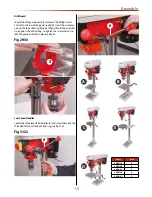
7. Slot the drill table (2e or 2f) into the machined hole to the
front of the mounting arm (2b and 2c) and screw a lift and shift
clamping handle (10) into to the threaded hole beneath the
table and tighten, see figs 12-13. Check it has ‘pinched’ up on
the drill table spigot and the drill table is immobile.
Radial and Floor Standing Drills Only
Fig 12-13-14
Rise and fall rack
cup chamfer
Machined flat
9
10
2f
2e
Summary of Contents for AHDP13B
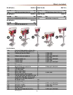
Page 4: ...What s Included 4 1 2 3 4a 2c 4 ...
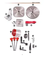
Page 5: ...What s Included 5 2b 2e 2d 2a 5 6 10 9 7 8 13 11 12 2f ...
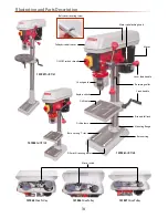
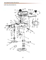
Page 24: ...Exploded Diagram Parts List 24 AHDP13B Bench Pillar Drill ZQJ4113A ...
Page 26: ...Exploded Diagram Parts List 26 AHDP16B Bench Pillar Drill ZQJ4116Q ...
Page 28: ...Exploded Diagram Parts List 28 AHDP16F Floor Pillar Drill ZQJ4116A ...
Page 34: ...Wiring Diagram 34 ...
Page 35: ...CE Certificate 35 AHDP13B Bench Pillar Drill ZQJ4113A AHDP16F Floor Pillar Drill ZQJ4116A ...
Page 36: ...CE Certificate 36 AHDP16B Pillar Drill ZQJ4116Q ...
Page 37: ...CE Certificate 37 AHRD16B Bench Radial Drill ZQJ3116 AHRD16F Floor Radial Drill ZQJ3116A ...
Page 38: ...Notes 38 ...
Page 39: ...Notes 39 ...


