Assembly
13
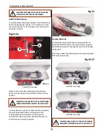
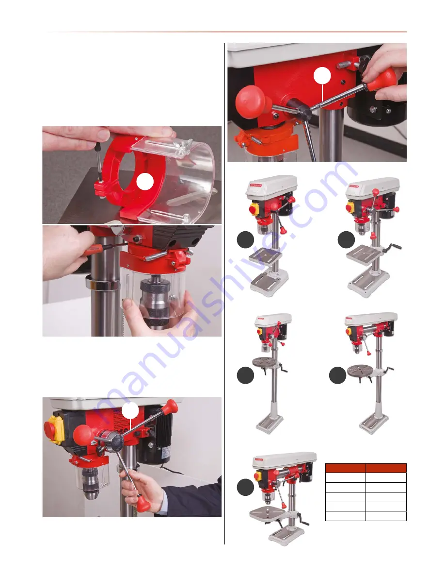
Drill Guard
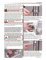
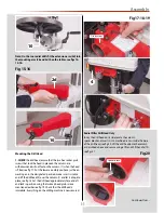
Locate the drill guard assembly (5), loosen the Phillips screw
and nut to the rear of the guard, see fig 29 insert the assembly
up over the lower bearing flange of the quill until the assembly
is up against the drill casting, re-tighten the screw and nut to
lock the guard assembly in place, see fig 30.
Fig 29-30
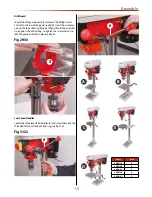
Lever Feed Handles
Locate the three lever feed handles (6) and screw them into the
threaded holes on the depth stop ring, see fig 31-32.
Fig 31-32
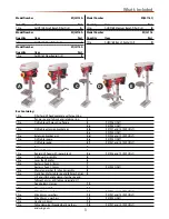
A
B
C
D
E
Model
Letter
AHDP13B
A
AHDP16B
B
AHDP16F
C
AHRD16B
D
AHRD16F
E
5
6
6
Summary of Contents for AHDP13B
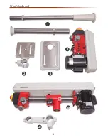
Page 4: ...What s Included 4 1 2 3 4a 2c 4 ...
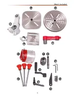
Page 5: ...What s Included 5 2b 2e 2d 2a 5 6 10 9 7 8 13 11 12 2f ...
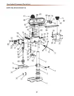
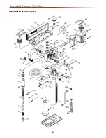
Page 24: ...Exploded Diagram Parts List 24 AHDP13B Bench Pillar Drill ZQJ4113A ...
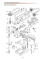
Page 26: ...Exploded Diagram Parts List 26 AHDP16B Bench Pillar Drill ZQJ4116Q ...
Page 28: ...Exploded Diagram Parts List 28 AHDP16F Floor Pillar Drill ZQJ4116A ...
Page 34: ...Wiring Diagram 34 ...
Page 35: ...CE Certificate 35 AHDP13B Bench Pillar Drill ZQJ4113A AHDP16F Floor Pillar Drill ZQJ4116A ...
Page 36: ...CE Certificate 36 AHDP16B Pillar Drill ZQJ4116Q ...
Page 37: ...CE Certificate 37 AHRD16B Bench Radial Drill ZQJ3116 AHRD16F Floor Radial Drill ZQJ3116A ...
Page 38: ...Notes 38 ...
Page 39: ...Notes 39 ...


