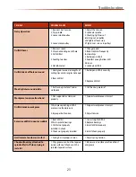
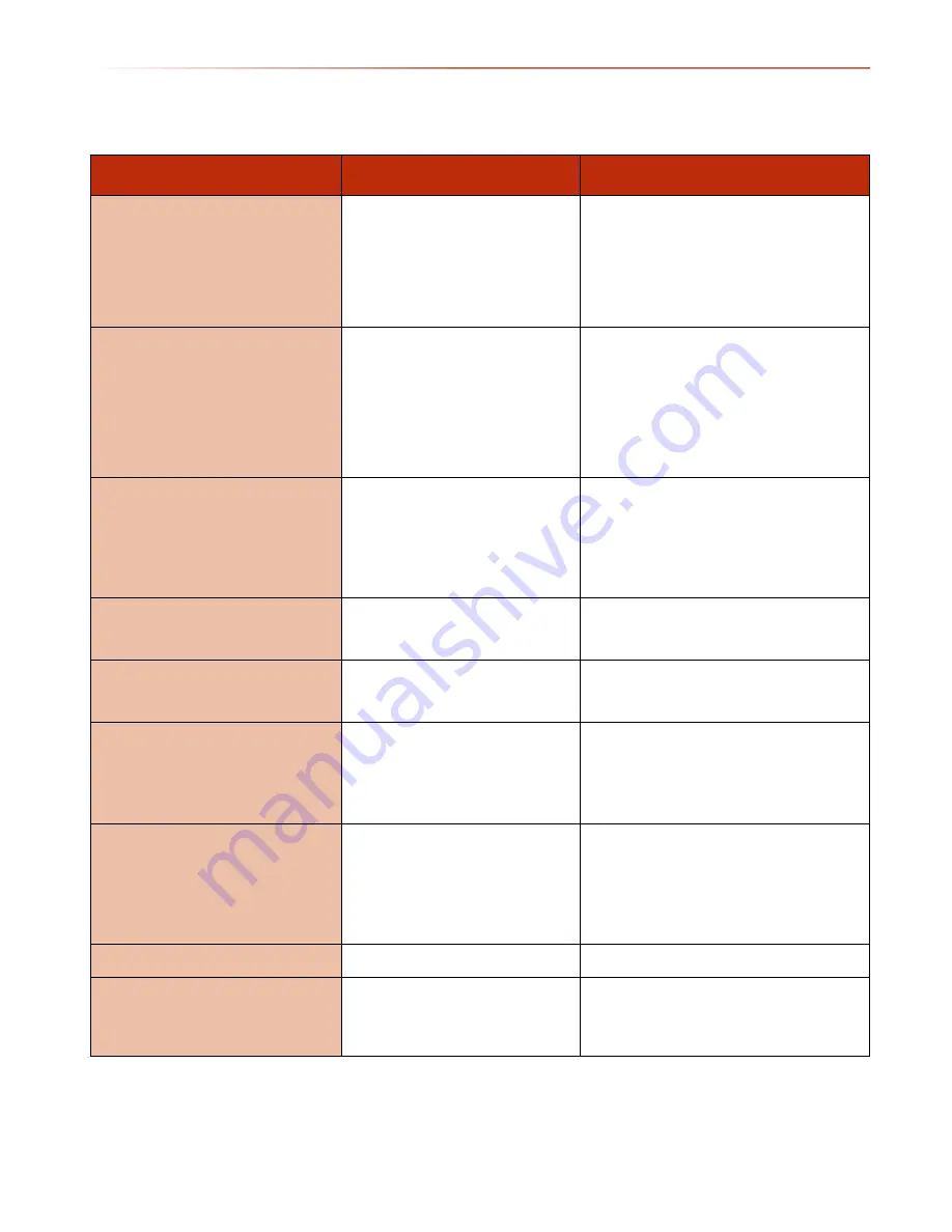
background image

Troubleshooting

23

TROUBLE

PROBABLE CAUSE

REMEDY

Noisy Operation

1. Incorrect belt tension
2. Dry spindle
3. Loose spindle pulley

4. Loose motor pulley

1. Adjust the tension 
2. Lubricate spindle 
3. Checking tightness of 
retaining nut on pulley, 
and tighten if necessary
4. Tighten set screws in pulleys

Drill bit burns

1. Incorrect speed 
2. Chips not coming out of hole
3. Dull drill bit

4. Feeding too slow

5. Not lubricated

1. Change speed 
2. Retract drill bit frequently 
to clear chips
3. Resharpen drill bit
4. Feed fast enough-allow drill 
bit to cut.
5. Lubricate drill bit

Drill bit leads off hole not round

1. Hard grain in wood or lengths of 
cutting lips and/or angles not equal 
 
2. Bent drill bit

1. Resharpen drill bit correctly 


2. Replace drill bit

Wood splinters on underside

1. No “back-up material” under 
workpiece

1. Use “back-up material” 

Workpiece torn loose from hand

1. Not supported or clamped 
properly

1. Support workpiece or clamp it

Drill bit binds in workpiece

1. Workpiece pinching drill bit
or excessive feed pressure 
 
2. Improper belt tension

1. Support workpiece or clamp it 
 
 
2. Adjust tension 

Excessive drill bit runout or wobble

1. Bent drill bit
2. Worn spindle bearings
3. Drill bit not properly
installed in chuck
4. Chuck not properly installed

1. Use a straight drill bit 
2. Replace bearings
3. Install drill bit properly  
 
4. Install chuck properly

Quill returns too slow or too fast

1. Spring has improper tension

1. Adjust spring tension

Chuck will not stay attached to 
spindle it falls off when trying to 
install it

1. Dirty, grease or oil on the tapered 
inside surface of chuck or on the 
spindles tapered surface

1. Make sure all surfaces are free of dust
and grease

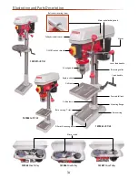
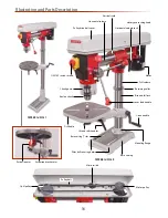
Summary of Contents for AHDP13B

Page 1: ...r manual AHDP13B Code 101925 AHDP16B Code 101926 AHDP16F Code 101927 AHRD16B Code 101928 AHRD16F Code 101929 AXMINSTER SERIES Hobby AT M 27 10 2016 REF 101974 Code 101925 Code 101926 Code 101927 Code 101928 Code 101929 ...

Page 2: ...rrect safety procedures when using this machine Fully read manual and safety instructions before use Eye protection should be worn Ear protection should be worn HAZARD Motor gets hot Dust mask should be worn Index of Contents 02 Declaration of Conformity 03 What s Included 04 05 06 General Safety Instructions 06 07 General Safety Instructions for Drilling Machines 07 Specification 08 Assembly 09 1...

Page 3: ... ONLY 2c 101928 ONLY 1 No Extension bracket arm 2d 101928 and 101929 ONLY 1 No Drill table square 2e 101928 ONLY Drill table round 2f 101927 and 101929 ONLY 1 No Base 3 1 No Pillar drill head 4 1 No Radial drill head with spacer block 4a 101928 and 101929 ONLY 1 No Drill guard assembly 5 3 No Lever feed handles 6 1 No Keyless chuck 3 16mm 7 Keyless chuck 1 13mm 7 101925 ONLY 1 No Morse taper arbor...

Page 4: ...What s Included 4 1 2 3 4a 2c 4 ...

Page 5: ...What s Included 5 2b 2e 2d 2a 5 6 10 9 7 8 13 11 12 2f ...

Page 6: ...ne General Instructions for 230VTools GoodWorking Practices Safety The following suggestions will enable you to observe good working practices keep yourself and fellow workers safe and maintain your tools and equipment in good working order WARNING KEEPTOOLS AND EQUIPMENT OUT OFTHE REACH OFYOUNG CHILDREN Work Place Environment DO NOT use when or where it is liable to get wet If the machine is to b...

Page 7: ...rills are the correct type and size are undamaged and are kept clean and sharp this will maintain their operating performance and lessen the loading on the machine Above all OBSERVE make sure you know what is happening around you and USEYOUR COMMON SENSE General Safety Instructions for Drilling Machines 1 DO NOT operate the machine without carrying out a preliminary inspection 2 CHECK that the spe...

Page 8: ...500rpm Swing 210mm Chuck Size 1 5 13mm Keyless Chuck Travel 50mm Diameter of Column 46mm Max Chuck to Table 285mm Max Chuck to Base 380mm Table Tilt 45 to 45 Base Size 285 x 185mm Collar Diameter 46mm Quill Diameter 45mm Table Size 165 x 165mm Overall L x W x H 500 x 280 x 735mm Weight 26kg Code 101926 Model AHDP16B Power 375W 50Hz 230V 1 ph Speed Range 12 210 2 580rpm Swing 254mm Chuck Cap Type 3...

Page 9: ...ption to identify the parts quickly and easily WARNING THE DRILL HEAD IS A HEAVY AND SUBSTANTIAL PIECE OF MACHINERY YOU ARE ADVISEDTO HAVE HELPTO LIFT IT CLEAR OFTHE BOX AND FIT ITTOTHE COLUMN 1 Place the base 3 on the bench or floor and place the mounting flange of the column 1 onto the seating flange of the base align the holes Use the four Hex bolts and secure the column to the base see fig 1 L...

Page 10: ...the column and can swivel around the pillar Locate the lift and shift clamping handle 10 and screw it into the threaded hole to the rear of the mounting bracket arm 2 and tighten see fig 11 Check it has pinched up on the column and the bracket is immobile both in its up and down travel and swivel movement Fig 11 7 Slot the drill table 2e or 2f into the machined hole to the front of the mounting ar...

Page 11: ...ead 4 over the column 1 and let it drop into place see fig 18 Set the drill head approximately fore and aft and lock in position using the two cap head grub screws mentioned earlier see fig 19 Check that the drillhead is immobile Everything on the drilling machine is now secured Mounting the Drill Head Fig 17 18 19 2 Lay the drill head on its side locate the column spacer block and insert it into ...

Page 12: ...t see fig 23 24 25 For the floor standing pillar drill head move the tensioning lever back then re tighten the motor yoke locks to lock the motor in place see fig 24 25 Fig 25 26 Fig 25 26 1 13mm Keyless Chuck AHDP13B Only 3 16mm Keyless Chuck Locate the chuck 7 and insert it up over the morse taper arbor using a high faced mallet lightly tap it home Locate the morse taper arbor 8 insert the arbor...

Page 13: ...lange of the quill until the assembly is up against the drill casting re tighten the screw and nut to lock the guard assembly in place see fig 30 Fig 29 30 Lever Feed Handles Locate the three lever feed handles 6 and screw them into the threaded holes on the depth stop ring see fig 31 32 Fig 31 32 A B C D E Model Letter AHDP13B A AHDP16B B AHDP16F C AHRD16B D AHRD16F E 5 6 6 ...

Page 14: ...ey 101927 AHDP16F Pulley drive belt cover Motor yoke locking knob Motor Belt cover securing screw Lever feed handle Retaining collar Crank handle Rise and fall rack Mounting flange Base casting Micro switch Drill table Keyless chuck Chuck guard ON OFF switch shroud Drill column Base casting T slot Pillar drill securing holes ...

Page 15: ... Emergency stop button B Motor yoke clamp A Table tilt locking bolt 90 Locking bolt Motor yoke clamp A Drive belt tensioning lever B Table tilt scale A Table tilt pointer B Depth stop assembly A Depth stop scale B Depth stop nuts C Pointer D Quill rise and full return spring A B A C A B B A A B A B A A C D B ...

Page 16: ...er feed handle Retaining collar Crank handle Rise and fall rack Mounting flange Lift and shift handles Base casting T slot Base casting Motor pulley Pulley belt Quill pulley Pillar drill securing holes Drill table Extension arm Extension bracket arm Keyless chuck Chuck guard ON OFF switch shroud Drill column 101929 AHRD16F 101928 AHRD16B Micro switch ...

Page 17: ...he column forward Turn the horizontal adjusting knob clockwise to move the column back Vertical locking pin Loosen the horizontal column clamping handle B Pull out the vertical locking pin to un lock the drill head column Rotate or to the appropriate angle using the tilt pointer on the column then retighten the horizontal clamping handle to lock the head in position Table tilt scale A Table tilt p...

Page 18: ...THE BELT ONTHE PULLEYS WARNING TAKE CARE NOTTOTRAPYOUR FINGERS WHEN REPOSITIONINGTHE BELT ONTHE PULLEYS Turn the pulley train see fig 35 to check the belts move freely Tension the whole belt train by turning the drive belt tensioning lever B anti clockwise to move the motor assembly out Tighten the motor yoke butterfly knobs A to lock the motor assembly in position Fig 35 A B To release the tensio...

Page 19: ... CHECK THE DRILL RUNS SMOOTHLY NO HARDVIBRATION ETC If all seems satisfactory recommence drilling operations Removing the Keyless Chuck Motor yoke lock 1 Lower the quill to its maximum depth by turning the lever feed handle While holding the handle turn the depth scale ring A fully round and then tighten the butterfly depth stop clamp B to lock the quill in position see fig 40 Fig 40 2 Place a pie...

Page 20: ...ck If the machine is going to stand idle for any length of time a light coat of spray or machine oil over the column and table will prevent rusting Then place a dust sheet over the pillar drill WARNING DISCONNECTTHE MACHINE FROMTHE MAINS SUPPLY BEFORE CONTINUING Cleaning WARNING DO NOT USETHE MACHINE IFTHE POWER CABLE HAS BECOME DAMAGED Electric If any servicing other than the above cleaning becom...

Page 21: ...tTables 21 5 Speed 101925 AHDP13B Bench Pillar Drill 12 Speed 101926 AHDP16B Bench Pillar Drill 101927 AHDP16F Floor Pillar Drill 5 Speed 101928 AHRD16B Bench Radial Pillar Drill 101929 AHRD16F Floor Pillar Drill ...

Page 22: ...4 0 7 16 2 8 3 32 2 4 1 16 1 6 1 32 0 8 1580 1750 1870 rpm 3 8 9 5 1 4 6 4 7 32 5 6 3 16 4 8 1 8 3 2 3 32 2 4 1 16 1 6 3 64 1 2 1250 1290 1330 rpm 5 8 15 9 3 8 9 5 11 32 8 7 5 16 7 9 1 4 6 4 5 32 4 0 1 8 3 2 1 16 1 6 790 830 900 rpm 7 8 22 2 1 2 12 7 15 32 11 9 7 16 11 1 11 32 8 7 1 4 6 4 3 16 4 8 1 8 3 2 500 540 600 rpm 1 1 4 31 8 3 4 19 11 16 17 5 5 8 15 9 1 2 12 7 3 8 9 5 5 16 7 9 1 4 6 4 Spind...

Page 23: ...drill bit Wood splinters on underside 1 No back up material under workpiece 1 Use back up material Workpiece torn loose from hand 1 Not supported or clamped properly 1 Support workpiece or clamp it Drill bit binds in workpiece 1 Workpiece pinching drill bit or excessive feed pressure 2 Improper belt tension 1 Support workpiece or clamp it 2 Adjust tension Excessive drill bit runout or wobble 1 Ben...

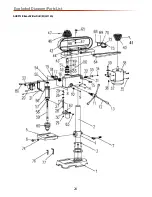
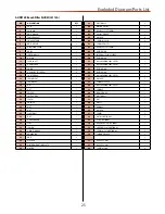
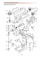
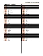
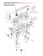
Page 24: ...Exploded Diagram Parts List 24 AHDP13B Bench Pillar Drill ZQJ4113A ...

Page 25: ...1 38 MOTOR 1 39 BOLT M8x16 2 40 MOTOR PULLEY 1 41 HEADLESS SET SCREW 1 42 PULLEY COVER 1 43 WASHER 4 44 SCREW M6X10 4 46 SPINDLE PULLEY 1 47 HEADLESS SET SCREW 1 48 RETAIN RING 1 49 INTERNAL SPLINE SLEEVE 1 50 RETAIN RING 1 51 BALL BEARING 6203 2RZ Z1 1 52 BALL BEARING 6203 2RZ Z1 1 53 RETAIN RING 1 54 RETAIN RING 1 55 BALL BEARING 6201 2RZ Z1 1 56 WASHER 1 57 SPINDLE SLEEVE 1 58 BALL BEARING 6201...

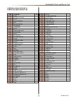
Page 26: ...Exploded Diagram Parts List 26 AHDP16B Bench Pillar Drill ZQJ4116Q ...

Page 27: ...OB 34 HEADLESS SET SCREW 35 NUT 36 BODY 37 HEX KEY 38 HEX KEY 39 HEADLESS SET SCREW 40 SLIDE BAR BOLT 41 SCREW 42 SLIDE BAR 43 INSTRUCTION MANUAL 44 CHUCK KEY 45 SPRING 46 SPRING SEAT 47 NUT 48 PLASTIC JAM NUT 49 SCREW 50 SWITCH 51 WIRE CLAMP 52 SCREW 53 MOTOR MOUNTING PLATE 54 MOTOR 55 BOLT 56 WASHER 57 NUT 58 V BELT 59 CENTRE PULLEY 60 HEADLESS SET SCREW 61 CHUCK GUARD 62 RETAIN RING 63 BALL BEA...

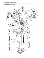
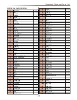
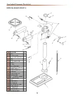
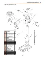
Page 28: ...Exploded Diagram Parts List 28 AHDP16F Floor Pillar Drill ZQJ4116A ...

Page 29: ... X 12 1 47 SWITCH MOTOR 1 48 SCREW M5 X 10 1 49 CLAMP CORD 1 50 BODY 1 51 HEX BOLT M8 X 16 1 52 SHIFTER 1 53 SLIDE BAR 1 54 SLIDE BAR 1 55 MOTOR BASE 1 56 WASHER M12 1 56a LOCK WASHER M12 1 57 NUT M12 1 58 MOTOR 1 59 MOTOR PULLEY 1 60 KEY 5 X 20 1 61 SETSCREW M6X 6 1 62 V BELT 4 63 CENTRE SHAFT 4 65 BALL BEARING 1 66 C CLIP 1 67 CENTRE PULLEY 1 68 WASHER M6 1 68b WASHER M6 1 69 SCREW M6 X 10 1 70 ...

Page 30: ...Exploded Diagram Parts List 30 AHRD16B Bench Radial Drill ZQJ3116 AHRD16F Floor Radial Drill ZQJ3116A ...

Page 31: ...DE ZQJ3116A 1 38 RETAINING RING 1 39 SET SCREW 1 40 GEAR 1 41 SPACER 2 42 KNOB 1 43 BRACKET 1 44 TENSION ADJUSTMENT BAR 2 45 HEX HEAD BOLT 4 46 8MM FLAT WASHER 4 47 MOTOR MOUNT PLATE 1 48 10MM FLAT WASHER 2 49 10MM LOCK WASHER 2 50 HEX NUT 2 51 MOTOR INCL REF NOS 52 54 1 52 CAPACITOR 1 53 STRAIN RELIEF 1 54 MOTOR CORD 1 55 LINE CORD 1 56 STRAIN RELIEF 2 57 6MM FLAT WASHER 4 58 PAN HEAD SCREW 4 59 ...

Page 32: ...BLE BRACKET ASSEMBLY INCL REF NOS 12 AND 21 1 10 WORM AND PINION GEAR SET 1 11 WORM GEAR 1 12 PINION GEAR AND SHAFT 1 13 LOCKING HANDLE 1 14 12 1 75 X 25MM HEX HEAD BOLT 1 15 12MM FLAT WASHER 1 16 ARM 1 17 LOCKING HANDLE 2 18 EXTENSION ARM 1 19 SQUARE TABLE 260 X 260MM 1 20 INDEX PIN AND NUT 1 21 6 1 0MM HEX NUT 1 22 SCALE WITH RIVETS 1 22 INDICATOR WITH RIVETS 1 AHRD16B Bench Radial Drill ZQJ3116...

Page 33: ...E BRACKET ASSEMBLY INCL REF NOS 12 AND 21 1 10 WORM AND PINION GEAR SET 1 11 WORM GEAR 1 12 PINION GEAR AND SHAFT 1 13 LOCKING HANDLE 1 14 12 1 75 X 25MM HEX HEAD BOLT 1 15 12MM FLAT WASHER 1 16 ARM 1 17 LOCKING HANDLE 2 18 EXTENSION ARM 1 19 ROUND TABLE 310MM DIAM ETER 1 20 INDEX PIN AND NUT 1 21 6 1 0MM HEX NUT 1 22 SCALE WITH RIVETS 1 22 INDICATOR WITH RIVETS 1 AHRD16F Floor Radial Drill ZQJ311...

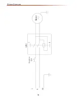
Page 34: ...Wiring Diagram 34 ...

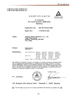
Page 35: ...CE Certificate 35 AHDP13B Bench Pillar Drill ZQJ4113A AHDP16F Floor Pillar Drill ZQJ4116A ...

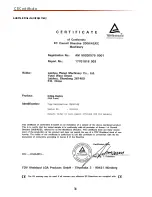
Page 36: ...CE Certificate 36 AHDP16B Pillar Drill ZQJ4116Q ...

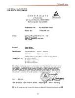
Page 37: ...CE Certificate 37 AHRD16B Bench Radial Drill ZQJ3116 AHRD16F Floor Radial Drill ZQJ3116A ...

Page 38: ...Notes 38 ...

Page 39: ...Notes 39 ...

Page 40: ... original product including original blades or abrasives The Axminster guarantee is available on Hobby Trade Industrial Engineer AirTools CNCTechnology Series machines It s probably the most comprehensive FREE guarantee ever buy with confidence from Axminster So sure are we of the quality we cover all parts and labour free of charge for three years Look for the icon and put your trust in Axminster...

Reviews: