background image

340297

AS408 Belt & Disc 
Sander

Axminster Reference

No: 

AS408

User Manual

W H I T E

A X M I N S T E R

W

w w w. a x m i n s t e r. c o . u k

Summary of Contents for AS408

Page 1: ...340297 AS408 Belt Disc Sander Axminster Reference No AS408 User Manual W H I T E AXMINSTER W www axminster co uk...

Page 2: ...ns 07 Assembly 08 09 10 11 12 13 14 Assembly Configurations 15 16 Illustration Parts Description 17 18 19 Sanding Configurations 20 Changing the Sanding Belt 21 Changing the Sanding Disc 22 Maintenanc...

Page 3: ...ng 1 off Table Support Steel Rod 1 off Table Adjustable 1 off Pastic Disc Guard Moulding 1 off 200mm Cast iron Disc Plate 1 off Workstop Plate 1 off Sanding Belt 1 off 200mm Sanding Disc Bag 1 4 off R...

Page 4: ...03 W H I T E AXMINSTER W www axminster co uk What s in the Box B C D E...

Page 5: ...ving unpacked your sander and its various components if you do not wish to retain the packaging please dispose of it responsibly especially any polystyrene most of the rest of the packaging is biodegr...

Page 6: ...machine to its own stand However you mount your machine make sure it is fastened down and stable before use Paper belts and discs do not respond well to wet or damp conditions In the worst case the a...

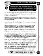
Page 7: ...MAKE SURE you are comfortable before you start work balanced not reaching etc If the work you are carrying out is liable to generate excessive grit or dust or chips wear the appropriate safety clothin...

Page 8: ...ves over the tracking drum do not press at all other than to keep the workpiece in contact with the surface any pressure could upset the tracking geometry As there is no cushioning effect to the belt...

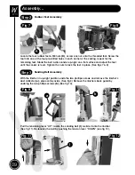
Page 9: ...beneath the linisher allowing the motor assembly to move freely Locate the drive belt b and slot the belt over both pulleys Note You my need to turn each pulley to fit the belt Fig 3 Fig 4 a b Hold th...

Page 10: ...ace and adjust the feet until the sander is level Tighten the nuts to lock the feet in place See figs 7 8 Fig 7 Fig 8 K Fig 9 With the linisher in up right position undo the two phillips screws and re...

Page 11: ...e of the linishing table See figs 13 14 NOTE You can wear a glove if you wish to stop the abrasive on the belt cutting your skin Replace the linishers back guard lower the linisher and clamp in place...

Page 12: ...ed hole in the casting See fig 17 insert the M5 x 50mm phillips screw and lightly tighten See fig 20 Fig 21 Fig 22 Machined hole F J G L Phillips screw Phillips screw 11 Find the phillips screw you re...

Page 13: ...24 25 G F Fig 25 Fig 26 Pre drilled hole Slide a phillips screwdriver down the hole tighten the screw to clamp the disc Locate the dust extraction moulding C line up the pre drilled holes with the ho...

Page 14: ...the table using the lower lift shift handle b See figs 30 31 32 Make sure the bubble is between the black lines Upper lift shift handle a Lower lift shift handle b Fig 31 Fig 32 D E E J J 13mm Spanner...

Page 15: ...t insert a jubilee clip over the hose and insert it over the outlet clamp in place Alternately if you have a vacuum cleaner with the same diameter holes insert it over the outlet as before it should b...

Page 16: ...raise the linisher clamp in place Loosen the bolt to the side of the sander insert the table support rod D into the machined hole tighten using a 14mm spanner See figs 40 41 Slide the table H onto th...

Page 17: ...before Remove the dust deflector a by removing the two phillips screws place safely aside See figs 44 45 Put to hand the workstop plate H you removed earlier offer up bracket see fig 43 to the thread...

Page 18: ...Iron Disc Plate B Mitre Fence H Workstop Plate C Dust Extraction Moulding I Sanding Belt D Table Support Steel Rod J 200mm Sanding Disc E Table K Rubber Feet F Plastic Disc Guard Moulding A B C D E F...

Page 19: ...n Parts Description F I A H B D K Motor Dust deflector Motor guard Spanners Linisher Linisher s back guard Linisher s back guard dust deflector plate Loosen the two phillips screws pull the deflector...

Page 20: ...19 W H I T E AXMINSTER W Illustration Parts Description Configuration 1 Table to Linisher Configuration 2 Workstop Plate used as miniature table Fig 49 Fig 50...

Page 21: ...W H I T E AXMINSTER W 20 Sanding Configurations Fig 53 Surface Sanding Curve Sanding Bevel Sanding Fig 52 Fig 51 Fig 54 Fig 55 Disc Sanding Belt Sanding...

Page 22: ...e belt NOTE1 All directions are given from the view point of the operator standing behind the drive drum end looking down the length of the machine The tracking control works as follows turning the tr...

Page 23: ...t frayed worn or loose Fig 56 Fig 57 There is very little mechanical maintenance that can be carried out on the machine Most prudent maintenance is preventative and concerned with keeping the machine...

Page 24: ...2 asked to be transferred to the Technical Sales department Machine slows down while sanding 1 Applying to much pressure to workpiece 1 Apply less pressure to sanding surface Sanding belt runs off pul...

Page 25: ...W H I T E AXMINSTER W 24 Parts Breakdown...

Page 26: ...25 W H I T E AXMINSTER W Parts List www axminster co uk...

Page 27: ...W H I T E AXMINSTER W 26 Parts List FREEPHONE 0800 371822...

Page 28: ...take the packaging to the local amenity tip and place into the appropriate recycling bin Do not dispose of electric tools together with household waste material In observance of European Directive 20...

Reviews: