W H I T E
A X M I N S T E R
W
Assembly...
Fig 13
Fig 14
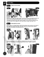
Tracking the Belt
NOTE1:
All directions are given from the view point of the operator standing behind the
drive drum end looking down the length of the machine. The tracking control works as
follows:- turning the tracking adjuster clockwise will track the belt to the right, anti-clockwise
will track the belt to the left.
NOTE2:
Using your hand, roll the belt towards the drive drum end, check that the belt
stays in the middle of the table, if not, adjust the track control slightly, and move the belt
again, continue until the belt runs down the centre of the linishing table (See figs 13 & 14).
NOTE: You can wear a glove if you wish, to stop the abrasive on the belt cutting your
skin.
Replace the linishers back guard & lower the linisher and clamp in place.
DO NOT MAKE LARGE ADJUSTMENTS, AND REMEMBER THE BELT MAY
TAKE SOME TIME TO REACT TO YOUR ALTERATION. LITTLE BY LITTLE IS A GOOD
MAXIM TO OBSERVE WHEN CARRYING OUT TRACKING OPERATIONS.
!
Workstop Plate Assembly
Step 4
Fig 15
Fig 16
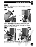
Locate the workstop plate
(H)
, remove the M10 bolt & spring washer using a 14mm spanner
(See fig 15). Mount the workstop plate over the linisher, secure using the M10 nut & spring
washer (See fig 15). Using a 90˚ square check that the workstop plate
(H)
is perpendicular
to the linisher (See fig 16), and make adjustments accordantly.
H
H
M10 bolt & Spring washer
10
90˚ Degree square


