background image

Parts Breakdown/List

29

Pillar Drill 700099 (WD13L) 

Summary of Contents for ED16B2

Page 1: ...Axminster Tool Centre Unit 10 Weycroft Avenue Axminster Devon EX13 5PH axminster co uk Pillar Drills Code 505024 Code 700100 Code 700099 Code 700101 ...

Page 2: ...119 3 Drill Press manufactured by Laizhou Light Industry Machinery Plant is in compliance with the following standards or standardisation documents in accordance with Council Directives DIN EN 60204 1 1998 11 Machinery Directive 98 37 EEC Annex 1 Amended 93 68 EEC The undersigned authorised by Laizhou Plant Machinery Co Ltd 989 North Lasi Zhou Road Laizhou Shandong declares that this product ZQJ41...

Page 3: ...ly 6 1 No Drill guard with Phillips screws 7 1 No Crank handle for table rise and fall mechanism 8 Bag Containing 2 No Motor yoke butterfly knobs 9 700101 ONLY 2 No M8 x 20mm Hex bolt and washers 700101 ONLY 3 No M8 x 20mm Hex bolt and washers 700099 ONLY 4 No M10 x 25mm Hex bolts spring and plain washers 505024 and 700100 ONLY 1 No 3 5 6mm Hex keys 10 1 No 3mm Hex key 10 700099 Only 1 No Morse ta...

Page 4: ...What s Included 4 1 6 5 2 4 7 11 13 9 10 12 8 3 Guard shield and screws inside the pulley drive belt cover ...

Page 5: ... moulded 13 Amp Plug and 3 core power cable Before using the machine inspect the cable and the plug to make sure that neither are damaged If any damage is visible have the machine inspected repaired by a suitably qualified person If it is necessary to replace the plug it is preferable to use an unbreakable type that will resist damage Only use a 13 Amp plug make sure the cable clamp is tightened s...

Page 6: ...g in these areas THIS IS NOT ONE OF THEM CHECK that drills are the correct type and size are undamaged and are kept clean and sharp this will maintain their operating performance and lessen the loading on the machine Above all OBSERVE make sure you know what is happening around you and USE YOUR COMMON SENSE General Safety Instructions for Drilling Machines 1 Do not operate the machine without carr...

Page 7: ...Power 250W Speed Range 5 600 2 500rpm Throat 105mm Chuck Cap Type 13mm keyless Chuck Travel 50mm Max Chuck to Table 215mm Max Chuck to Base 370mm Table Size 160 x 160mm Table Tilt 45 0 45 Base Size 290 x 180mm Overall L x W x H 240 x 470 x 735mm Weight 20kg Specification may have been used in setting up operations and put them away in their correct stowage positions 7 Try to arrange the drilling o...

Page 8: ...the column until the rise and fall rack is located in the cup chamfer in the top of the mounting flange see figs 9 10 Replace the cup chamfered retaining collar over the column and slide it down onto the top of the rack Lock it in place with the grub screw ensuring that it has captured the upper end of the rack securely but not too tight that the rack can not be swivelled around the pillar see fig...

Page 9: ...r Take the chuck guard and fit to the lower bearing flange of the quill mounting Tighten the screw and nut fastening so that the drill guard is securely held in place see fig 19 3 2 4 Mounting flange Retaining collar Top of rack Hex Bolts Grub screw Worm drive shaft Machined flat 8 ...

Page 10: ...Assembly 10 Fig 09 10 Fig 11 Fig 12 Fig 13 Pinion Rise and fall rack Bristol clamping handle Bristol clamping handle Cup chamfer 4 3 5 4 Grub screw Grub screw ...

Page 11: ... Fit the guard assembly to the lower bearing flange of the quill mounting tighten the screw and nut so that the drill guard is securely held in place Morse taper arbor and chuck Locate the morse taper arbor 11 and the B16 keyless chuck 13 Insert the arbor into the keyless chuck as shown in fig 20 Insert the other end of the arbor 11 up into the lower bearing flange in the quill until the assembly ...

Page 12: ... as shown Fig 21 Insert the other end of the arbor up into the quill until the assembly locks in place Lower bearing flange Morse taper arbor Place the mounting flange of the column 3 onto the seating flange of the base Align the holes Locate the two M8 Hex bolts you removed earlier from the drill head and the extra hex bolts and 8mm plain washers and secure the column to the base with a 13mm span...

Page 13: ... to its preferred workplace nothing should slew during the lift and move Once the drilling machine is correctly positioned and fastened down it is ready for use WARNING The drillhead is a heavy and substantial piece of machinery you are advised to have help Fig 25 26 Line up the three pre drilled holes and secure with the Phillips screws Guard moulding Pre drilled hole Fig 27 Keyless chuck Insert ...

Page 14: ...Drill table Chuck guard Light switch On Off switch shroud Motor Motor yoke locking knob Crank handle Rise and fall rack Mounting flange Base casting Micro switch Drill column Table clamping handle Retaining collar Lever Feed handle Pulley drive belt cover Quill Pulley Motor Pulley Jockey Pulley Drive belt tensioning ...

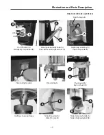
Page 15: ...lar drill light Table tilt pointer A Table tilt scale B Chuck guard A Keyless chuck B Table clamping handle A Table tilt clamping bolt B B A A A B B On Off switch A Emergency stop button B Motor yoke butterfly knob A Drive belt tensioning lever lock B Depth stop assembly A Depth stop scale B B A B B A A OFF ON Depth stop nuts ...

Page 16: ... handle Rise and fall rack Mounting flange Base casting Motor pulley Quill pulley Micro switch Pulley belt Retaining collar Lever Feed handle Drill table Chuck guard Depth stop clamp On Off switch shroud Drill column Table clamping handle Pulley drive belt cover 700101 ED16SB B16 Keyless Chuck ...

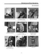
Page 17: ...rfly locking knob Table tilt clamping bolt Drill table mounting bracket clamping handle On Off switch A Emergency stop button B Table clamping handle Table tilt pointer A Table tilt scale B Depth scale A Depth scale pointer B Depth stop butterfly clamp Chuck guard A A A B B B ...

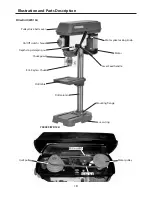
Page 18: ...or Motor yoke locking knob Depth stop clamping nut Mounting flange Base casting Lever Feed handle Pulley drive belt cover Drill table Chuck guard On Off switch shroud B16 Keyless Chuck Drill column Motor pulley Quill pulley Micro switch Pulley belt 700099 WD13L ...

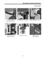
Page 19: ...l WD13L Drill table mounting bracket clamping handle Depth stop assembly A Depth stop scale B Motor yoke butterfly locking knob Chuck guard assembly Depth stop clamping screw nut Table tilt pointer A Table tilt scale B Depth stop nuts Pointer B B A A ...

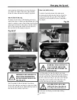
Page 20: ...to move the motor assembly in This will release the tension from the drive belts See figs 32 33 34 35 Pillar Drills ED16B2 and ED16F2 Only Fig 31 A B Turn the pulley train to check the belts move freely Tension the whole belt train by turning the drive belt Turn anti clockwise to slacken the belts Fig 32 33 34 35 Turn clockwise to tension the belts WARNING TAKE CARE NOT TO TRAP YOUR FINGERS WHEN R...

Page 21: ...PULLEYS Turn the pulleys to check the belts move freely Tension the pulleys by pushing the motor assembly out and securing the motor yoke butterfly knobs to lock the motor assembly in position Turn the pulleys to check the belts move freely Tension the pulleys by pushing the motor assembly out and securing the motor yoke butterfly knob to lock the motor assembly in position Lower the belt and pull...

Page 22: ...Speed Select Table 22 700099 WD13L Pillar Drill 7000101 ED16SB Pillar Drill 700100 ED16B2 505024 ED16F2 Pillar Drills ...

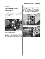
Page 23: ...ng damaged and lower the quill to it s maximum depth by turning the feed lever handle Fig 39 Pillar Drill ED16SB Only Pillar Drill ED16B2 ED16F2 Fig 40 Preparation Removing the chuck Morse taper arbor Quill slot Fig 41 You wil require the morse taper drift 12 A B While holding the handle in place turn the chuck to line up the morse taper arbor 11 in the quills machined slot See fig 40 Insert the m...

Page 24: ...ng of machine oil on the quill then to spread the oil If the machine is going to stand idle for any length of time a light coat of spray or machine oil over the column and table will prevent rusting WARNING DISCONNECT THE MACHINE FROM THE MAINS SUPPLY BEFORE CONTINUING WARNING DO NOT USE THE MACHINE IF THE POWER CABLE HAS BECOME DAMAGED WARNING DO NOT ATTEMPED TO REPAIR IT YOUR SELF CONTACT OUR TE...

Page 25: ...Parts Breakdown List 25 Pillar Drills 505024 ED16F 700100 ED16B2 ...

Page 26: ...SLIDE BAR WASHER MOTOR BASE NUT MOTOR PULLEY V BELT PULLEY COVER SET SCREW MOTOR KEY NUT WASHER HEX BOLT BODY CENTER SHAFT C CLIP BALL BEARING CENTER PULLEY C CLIP SCREW KNOB WASHER SPEED CHART LABEL SCREW WASHER HEX BOLT SHIFTER SET SCREW SET SCREW SET SCREW DEPTH RING FEED SHAFT HANDLE HANDLE COVER CAP BOLT V BELT SCREW SWITCH BOX SCREW WASHER WASHER SCREW SWITCH NUT SCREW SCALE SCALE BASE C CLI...

Page 27: ...Parts Breakdown List 27 Pillar Drill 700101 ED16SB ...

Page 28: ...Parts Breakdown List 28 Pillar Drill 700101 ED16SB ...

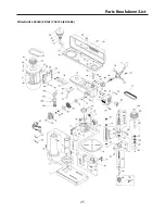
Page 29: ...Parts Breakdown List 29 Pillar Drill 700099 WD13L ...

Page 30: ...Parts Breakdown List 30 Pillar Drill 700099 WD13L ...

Page 31: ...Notes 31 ...

Page 32: ...ate recycling bin Do not dispose of electric tools together with household waste material In observance of European Directive 2002 96 EC on waste electrical and electronic equipment and its implementation in accordance with national law electric tools that have reached the end of their life must be collected separately and returned to an environmentally compatible recycling facility Only for EU co...

Reviews: