34
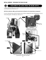
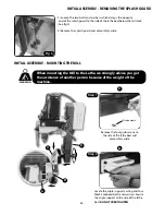
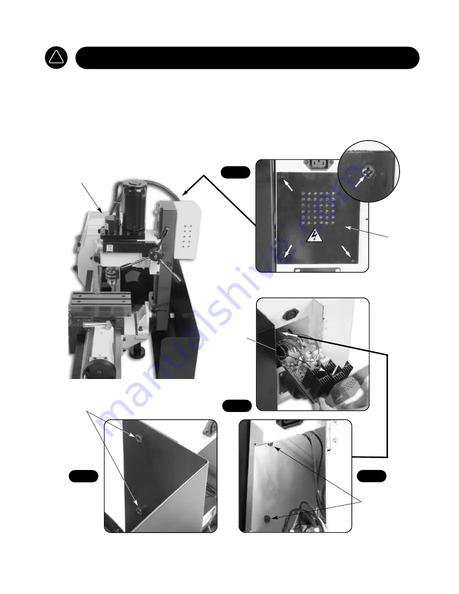
INITIAL ASSEMBLY - REMOVING THE SPLASH GUARD
1) Remove the four Phillip screws and pull out the electrical back plate to the rear of the lathe and lay the
circuit board to one side. (See fig 1 & 2 )
(NOTE. Be careful when lifting out the electrical circuit board as it contains delicate components)
2) Locate a 5mm allen key and 10mm spanner, remove the two caphead bolts and nuts that secures one side
of the splash guard to the headstock. ( See fig 3 & 4)
!
DISCONNECT THE LATHE FROM THE MAINS SUPPLY
Remove the four Phillip screws
and lift out the electrical panel
Electrical
back plate
Electrical
circuit
board
Headstock
Fig 2
Fig 3
Fig 4
Fig 1
Remove the two caphead bolts and nuts that secures one
side of the splash guard to the headstock
Two caphead bolts
Two 10mm nuts
Summary of Contents for SIEG SC6
Page 2: ...2 ...
Page 7: ...7 ...
Page 8: ...8 ...
Page 9: ...9 ...
Page 10: ...10 ...
Page 11: ...11 ...
Page 12: ...12 ...
Page 13: ...13 ...
Page 14: ...14 ...
Page 17: ...LATHE MAINTENANCE 17 ...
Page 18: ...18 ...
Page 19: ...19 ...
Page 20: ...20 ...
Page 21: ...21 ...
Page 22: ...22 SC6 WIRE DIAGRAM ...
Page 23: ...23 ...
Page 24: ...24 ...
Page 25: ...25 ...
Page 26: ...26 ...
Page 27: ...27 ...
Page 28: ...28 ...
Page 29: ...29 ...
Page 30: ...30 ...
Page 31: ...SIEG SC6 Mill Attachment ...
Page 46: ...MAINTENANCE OILING POINTS 46 Oil OIL ...
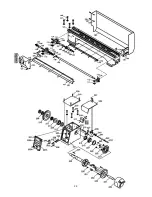
Page 48: ...PARTS BREAKDOWN FOR THE MILL 48 ...
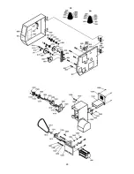
Page 49: ...PARTS BREAKDOWN FOR THE MILL 49 ...
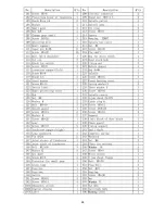
Page 50: ...50 PARTS LIST FOR THE MILL ...


