Assembly
10
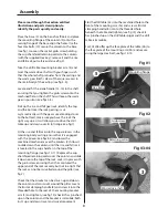
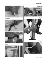
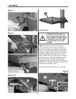
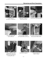
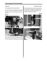
Fig 12
Fig 13
Fig 14-15
WARNING! THE DRILL HEAD IS A
HEAVY AND SUBSTANTIAL PIECE
OF MACHINERY, YOU ARE ADVISED
TO HAVE HELP TO LIFT IT CLEAR
OF THE BOX AND FIT IT TO THE
COLUMN.
PIllar drill head
CHECK the drill head, ensure that the two hex
socket grub screws that lock the head in place on
the column are withdrawn and will not foul on the
column (5) when the head is fitted (see fig 16). Put
the lower assembly you have just been working on
in the designated position, make sure it is stable
and lift the drillhead (1) over the column (5) and let
it drop into place. Set the drill head approximately
fore and aft and lock in position using the two
caphead grub screws mentioned earlier. Check that
the drillhead is immobile. Everything on the drilling
machine is now secured, see fig 17.
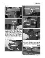
Locate the lever feed handle (7) and it’s securing
Fig 16
8
4a
8
4b
Large Hex bolt
Face plate
4b
1
Grub screw
Summary of Contents for Trade AT2001DP
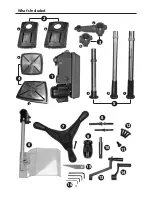
Page 4: ...What s Included 4 2 3 1 a a a a b b b c b 4 6 7 8 9 10 11 12 13 15 16 14 5 ...
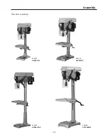
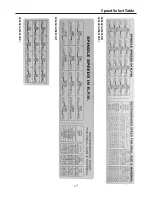
Page 17: ...Speed Select Table 17 505204 AT2801DP 505203 AT2001DP 505205 AT2801FDP 505206 AT3202FDP ...
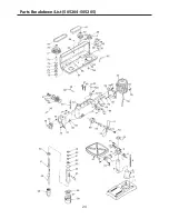
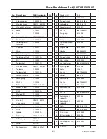
Page 21: ...Parts Breakdown List 505203 21 Continues Over ...
Page 24: ...Parts Breakdown List 505204 505205 24 ...
Page 27: ...Parts Breakdown List 505206 27 Continues Over ...
Page 30: ...Wiring Diagram 505203 505204 505205 30 ...
Page 31: ...Wiring Diagram 505206 31 ...


