Assembly
11
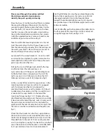
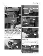
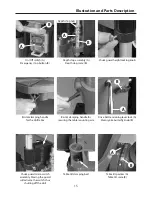
Fig 17
caphead bolt, note the raised boss of the feed
mechanism and the two spigots inside the feed
handle. Mount the handle over the boss and ensure
the spigots inside the handle (7) engages into the
machined slot in the boss. Secure with the supplied
caphead bolt through the hole in the centre of the
handle through to the tapped hole in the mounting
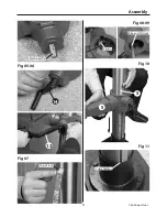
boss (see figs 18-19-20-21).
Fig 18-19-20-21
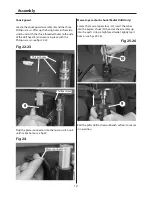
Pulley cover knob
Locate the pulley cover knob (11), remove the Phillips
screw, insert the screw through the pre-drilled hole
in the pulley cover and secure the knob in place, see
fig 22.
Fig 21
Continues Over...
Grub screw
Spigots
Raised boss
Threaded hole
Machined slot
7
7
11
Summary of Contents for Trade AT2001DP
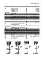
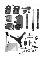
Page 4: ...What s Included 4 2 3 1 a a a a b b b c b 4 6 7 8 9 10 11 12 13 15 16 14 5 ...
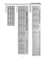
Page 17: ...Speed Select Table 17 505204 AT2801DP 505203 AT2001DP 505205 AT2801FDP 505206 AT3202FDP ...
Page 21: ...Parts Breakdown List 505203 21 Continues Over ...
Page 24: ...Parts Breakdown List 505204 505205 24 ...
Page 27: ...Parts Breakdown List 505206 27 Continues Over ...
Page 30: ...Wiring Diagram 505203 505204 505205 30 ...
Page 31: ...Wiring Diagram 505206 31 ...


