Assembly
12
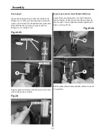
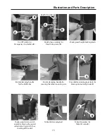
Chuck guard
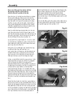
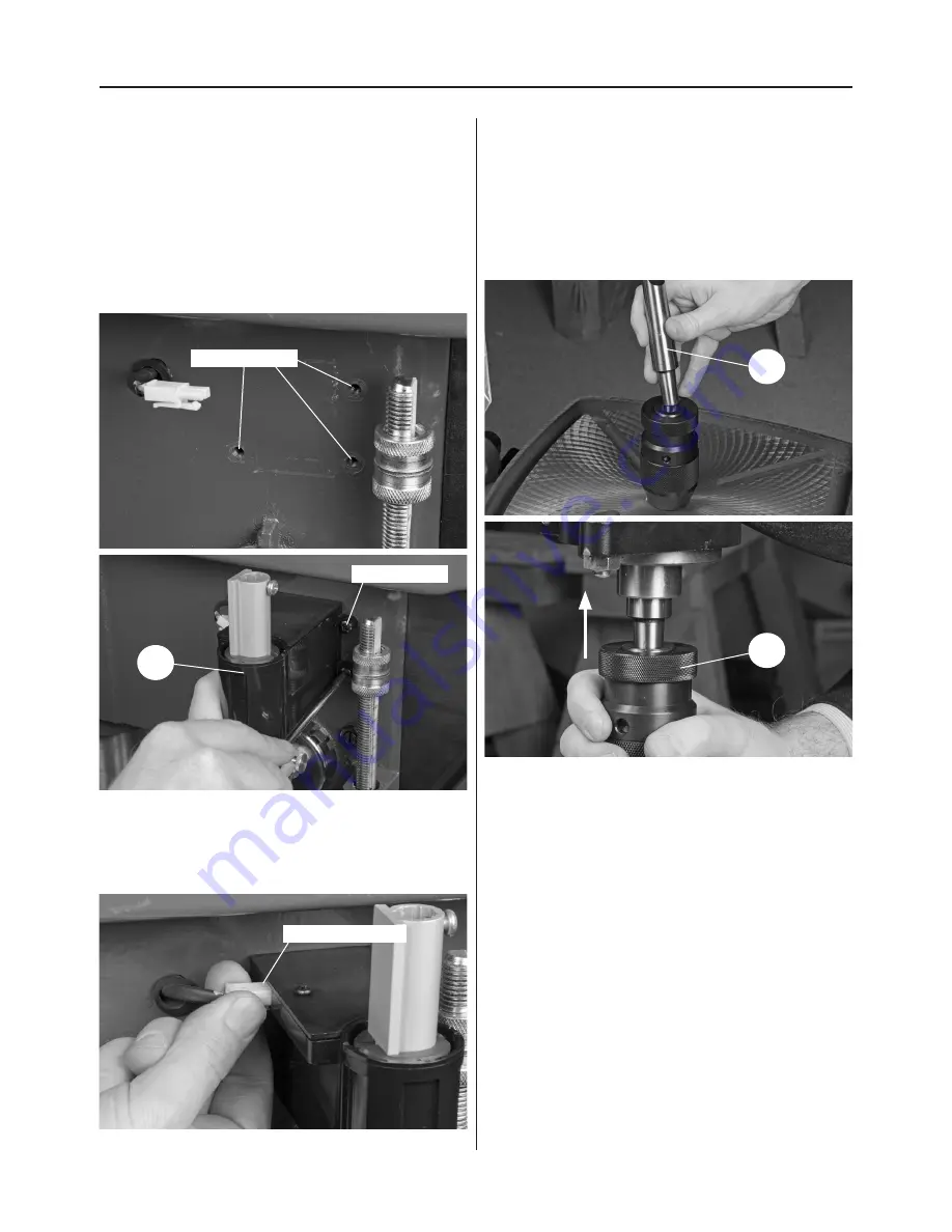
Locate the chuck guard assembly (6) and the three
Phillips screws. Offer up the fixing holes in the micro
switch unit with the three threaded holes to the side
of the drill head (1) and secure in place with the
Phillips screws, see figs 22-23
Fig 22-23
Plug the power connector into the micro switch unit,
unitl it clips home, see fig 24.
Fig 24
6
Thread holes
Phillips screw
Power connector
Morse taper arbor & chuck (Radial Drills Only)
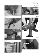
Locate the morse taper arbor (10), insert the arbor
into the keyless chuck (9) then slot the assembly up
into the quill. Using a high faced mallet, lightly tap it
home. (see figs 25-26)
Fig 25-26
10
9
Bolt the pillar drill to the workbench or floor to secure
it in position.
Summary of Contents for Trade AT2001DP
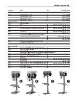
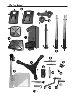
Page 4: ...What s Included 4 2 3 1 a a a a b b b c b 4 6 7 8 9 10 11 12 13 15 16 14 5 ...
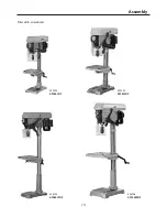
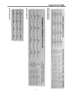
Page 17: ...Speed Select Table 17 505204 AT2801DP 505203 AT2001DP 505205 AT2801FDP 505206 AT3202FDP ...
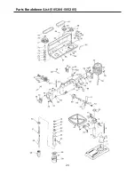
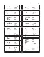
Page 21: ...Parts Breakdown List 505203 21 Continues Over ...
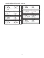
Page 24: ...Parts Breakdown List 505204 505205 24 ...
Page 27: ...Parts Breakdown List 505206 27 Continues Over ...
Page 30: ...Wiring Diagram 505203 505204 505205 30 ...
Page 31: ...Wiring Diagram 505206 31 ...


