Illustration & Parts Description
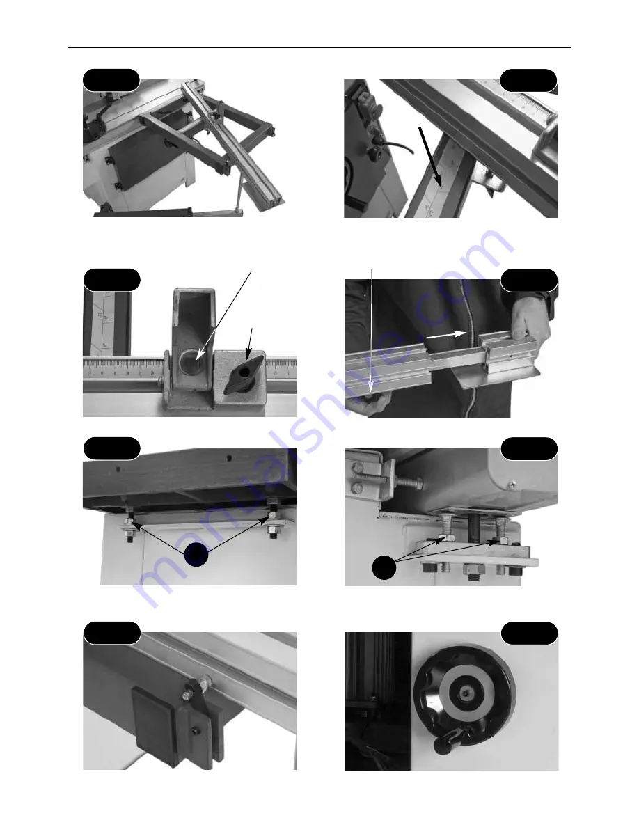
The extension table fence set to 45˚
Extension table angle scale
Fig 47
Fig 48
Distance stop assembly
Telescopic extension assembly
Fig 49
Fig 50
Magnifying glass
Butterfly clamping knob
Spindle moulder table height
adjusting nuts (a)
Sliding table height adjusting nuts (b)
Fig 51
Fig 52
a
b
Extension table 90˚ stop
Spindle tilt operating handle, located
to the front of the machine
Fig 53
Fig 54
21
Distance
stop clamp
Summary of Contents for WS1000TA
Page 4: ...04 What s Included A B B1 B2 B3 B4 B5 B6 B7 ...
Page 5: ...05 What s Included C D E E1 E2 E3 E4 E5 D1 D2 D3 C1 C2 C3 ...
Page 30: ...30 Trouble Shooting DISCONNECT THE MACHINE FROM THE MAINS SUPPLY ...
Page 31: ...31 Wiring Diagram ...
Page 32: ...32 Parts List Drawings ...
Page 33: ...33 Parts List Drawings ...
Page 34: ...34 Parts List Drawings ...
Page 35: ...35 Parts List Drawings ...
Page 36: ...36 Parts List Drawings ...
Page 37: ...37 Parts List Drawings ...
Page 38: ...38 Parts List Drawings ...
Page 39: ...39 Parts List Drawings ...
Page 40: ...40 Parts List Drawings ...
Page 41: ...41 Parts List Drawings ...
Page 42: ...42 Parts List Drawings ...
Page 43: ...43 Parts List Drawings ...


