22
Setting Up the Machine
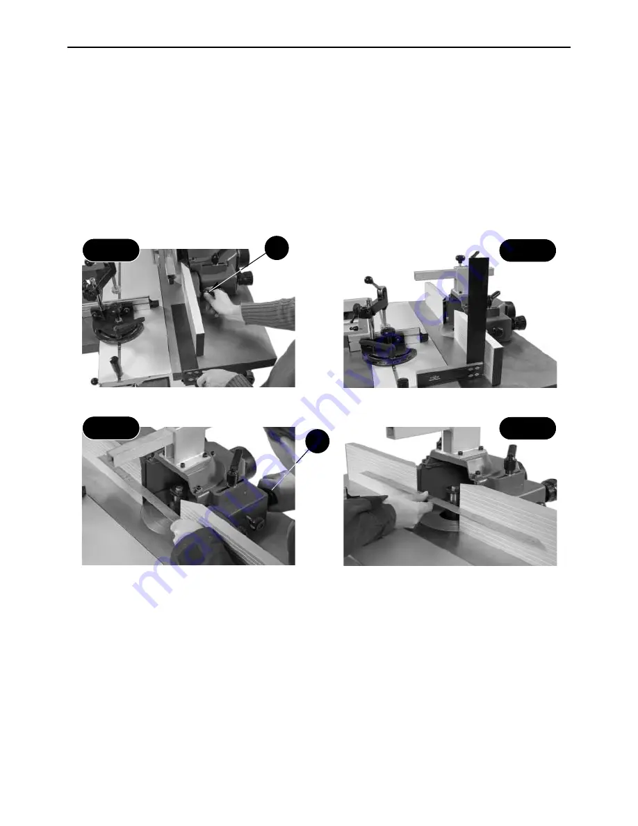
Place a 90˚square up against the fence and check it is perpendicular
Fig 55
Fig 56
Adjust the advancing knobs (b) until both
fences are aligned
Place a straight edge up-against the fences
and check they are aligned
Fig 57
Fig 58
The fence is a two piece adjusting system. Each fence is independently adjustable to compensate for different
cutting thicknesses.
Make sure the fence is square to the work surface, place a 90˚ square up against the fence and check it is
perpendicular to the work surface. If it is not, turn the fence adjusting knob
(a)
until it is correct (See figs 55
and 56).
Place a straight edge up-against the fence, loosen the fence advancing clamping knobs & turn the fence
advancing knobs
(b)
until both fences are aligned (See figs 57 & 58).
Setting the fence
A
B
Adjust the position of the fence assembly to give both the required cutter protrusion and adequate clearance
between the cutter and the fence. Close up the aluminum fences to give approximately 5mm clearance around
the cutter (see fig 59).
The fence is used to guide small workpieces through the cutter without them being trapped between the fence
and the cutter. The dust extraction hose is connected to the aperture at the rear of the fence casting.
Before starting work, carefully check that the cutter can rotate freely without fouling the inside of the guard and
that the guard is clamped firmly in place.
Summary of Contents for WS1000TA
Page 4: ...04 What s Included A B B1 B2 B3 B4 B5 B6 B7 ...
Page 5: ...05 What s Included C D E E1 E2 E3 E4 E5 D1 D2 D3 C1 C2 C3 ...
Page 30: ...30 Trouble Shooting DISCONNECT THE MACHINE FROM THE MAINS SUPPLY ...
Page 31: ...31 Wiring Diagram ...
Page 32: ...32 Parts List Drawings ...
Page 33: ...33 Parts List Drawings ...
Page 34: ...34 Parts List Drawings ...
Page 35: ...35 Parts List Drawings ...
Page 36: ...36 Parts List Drawings ...
Page 37: ...37 Parts List Drawings ...
Page 38: ...38 Parts List Drawings ...
Page 39: ...39 Parts List Drawings ...
Page 40: ...40 Parts List Drawings ...
Page 41: ...41 Parts List Drawings ...
Page 42: ...42 Parts List Drawings ...
Page 43: ...43 Parts List Drawings ...


