09
Assembly
Unpack all the boxes and check all the components
against the “What's in the Boxes' List. If any parts or
components are missing, please contact our customer
services department using the procedures and
telephone numbers listed in our catalogue, and you
will be dealt with quickly and efficiently.
Having unpacked the boxes, (please dispose of any
unwanted packaging responsibly), put the parts and
components whereby they are readily to hand. Break
down the main box by knocking the sides away (be
careful of exposed nails etc.), but leave the machine
sitting on its pallet. Remove the protective grease film
that is coating all the unpainted parts of the machine.
Use a proprietary de-greasing agent or paraffin et al.
Unfortunately, this cleaning process is always a bit
‘mucky’ especially if you tackle the job with a high level
of enthusiasm. You are advised to wear overalls or
coveralls etc., during the process. After cleaning,
especially if you used paraffin, lightly coat the exposed
metal surfaces to prevent any rusting.
Note: The WS1000TA spindle moulder comes 95%
assembled, in order to reduce the footprint of the
machine for packaging, several items are
dismounted from the machine and need to be
re-affixed.
PLEASE NOTE. Some of this assembly procedure is best accomplished by two persons.
Although the tasks are not impossible, some of the items are heavy and awkward, and a
mishandling error could cause injury. Please think about what you are doing, your
capabilities and your personal safety.
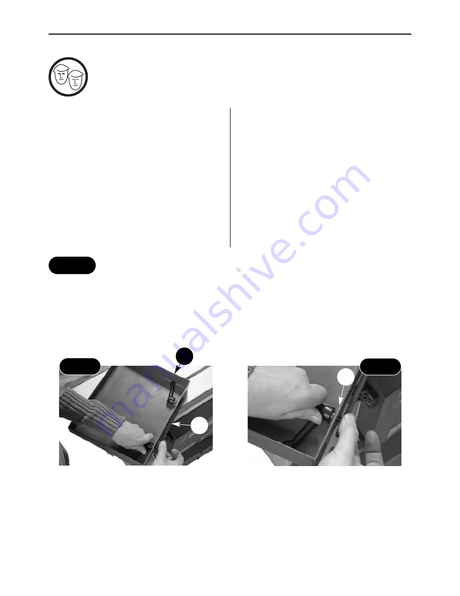
Screw the two lift and shift handles
C2
through
the both
C1
&
C3
Keep at lest a 3mm gap between the steel plate
C3
and support table
C1
Fig 1
Fig 2
Support Table Assembly
Locate the support table (
C1)
, the two lift and shift handles with M8 washer
(C2)
& the pre-drilled steel plate
(C3)
. Line up the pre-drilled holes in the steel plate
(C3)
with holes in the bench casting
(C1)
and screw the two
lift and shift handles
(C2)
through. Note: leave at least a 3mm gap between the plate
(C3)
& the support table
(C1)
for the next stage (See figs 1 & 2).
C3
C2
C1
Step 1
Summary of Contents for WS1000TA
Page 4: ...04 What s Included A B B1 B2 B3 B4 B5 B6 B7 ...
Page 5: ...05 What s Included C D E E1 E2 E3 E4 E5 D1 D2 D3 C1 C2 C3 ...
Page 30: ...30 Trouble Shooting DISCONNECT THE MACHINE FROM THE MAINS SUPPLY ...
Page 31: ...31 Wiring Diagram ...
Page 32: ...32 Parts List Drawings ...
Page 33: ...33 Parts List Drawings ...
Page 34: ...34 Parts List Drawings ...
Page 35: ...35 Parts List Drawings ...
Page 36: ...36 Parts List Drawings ...
Page 37: ...37 Parts List Drawings ...
Page 38: ...38 Parts List Drawings ...
Page 39: ...39 Parts List Drawings ...
Page 40: ...40 Parts List Drawings ...
Page 41: ...41 Parts List Drawings ...
Page 42: ...42 Parts List Drawings ...
Page 43: ...43 Parts List Drawings ...


