92
•
Reference Section
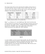
Thus, larger values of R
f
are more suited to patch recordings, where the noise is
more critical and the currents are smaller, whereas smaller values of R
f
are more
suited to whole-cell recordings, with their larger currents. The following table
summarizes these properties for different values of R
f
.
Feedback Resistor
Experiment Type
Range
Noise*
50 M
Ω
Whole Cell
1-200 nA
3.0 pA rms
500 M
Ω
Whole Cell
0.1-20 nA
1.4 pA rms
5 G
Ω
Patch
10-2000 pA
0.9 pA rms
50 G
Ω
Patch
0.2-200 pA
0.28 pA rms
*Bandwidth 10 kHz using an 8-pole Bessel filter. Noise is measured with the headstage open-circuit;
i.e.
it
represents the best possible intrinsic noise of the headstage circuitry.
Note:
V
cmd
is limited to 10 V in the MultiClamp 700B, which in turn limits the
maximum amount of current that can be injected through the headstage resistor into
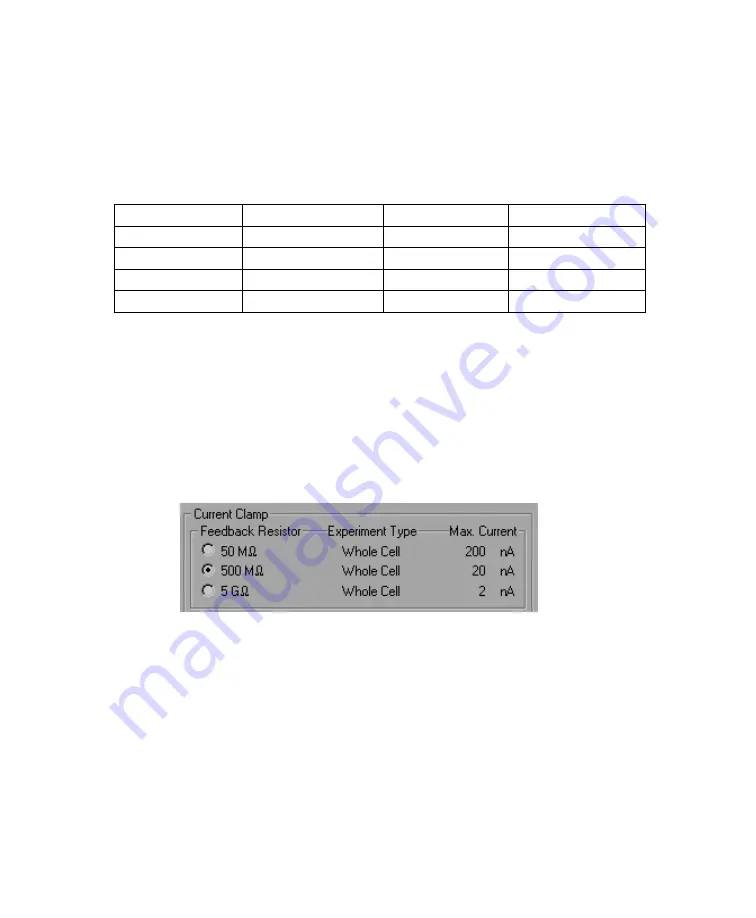
the electrode. For example, with R
f
= 500 M
Ω
, the maximum current that can be
injected is 10 V/500 M
Ω
= 20 nA. These current limits are listed in the
Options/Gains panel of the MultiClamp 700B Commander.
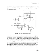
Figure 5.9
As a rule of thumb, it is best to use the largest possible value of R
f
without risk of
saturation. Be aware that incompletely compensated capacitance transients, which
are brief and often hard to see, may saturate before ionic currents. The
OVERLOAD LED on the front panel of the MultiClamp 700B will assist you in
judging when saturation has occurred.
MultiClamp 700B Theory and Operation, Copyright 2005 Axon Instruments / Molecular Devices


