94
•
Reference Section
principles that will assist you in choosing the filter type and cutoff frequency that
are most suited to your experiments.
-3 dB Frequency
The –3 dB, or cutoff, frequency (f
c
) of a filter is the frequency at which the output
signal
voltage
(or
current
) is reduced to 1/
√
2 (
i.e.
0.7071) of the input.
Equivalently, f
c
is the frequency at which the output signal
power
is reduced to half
of the input. These terms arise from the definition of decibel (dB):
Voltage: dB = 20 log(Vout/Vin)
Power:
dB = 10 log(Pout/Pin)
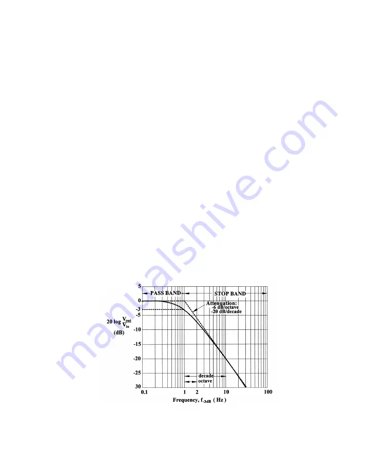
For a low-pass filter, the frequency region below f
c
is called the pass band, while
that above f
c
is called the stop band. In the stop band, the signal attenuates (or ‘rolls
off’) with a characteristic steepness. (See Figure 5.10, noting the logarithmic
frequency axis.) The steepness of the roll-off at higher frequencies is determined
both by the type of filter (see below) and the number of poles of the filter: the larger
the number of poles, the faster the roll-off. The low-pass on the Primary Output of
the MultiClamp 700B are 4-pole filters. Filters with more poles can be constructed,
but they are more complex to implement and yield diminishing returns.
MultiClamp 700B Theory and Operation, Copyright 2005 Axon Instruments / Molecular Devices
Figure 5.10
. Filter characteristics, illustrated for a single-pole, low-pass filter. The spectrum
has been normalized so that the signal magnitude in the pass band is 0 dB. The –3 dB frequency
has been normalized to unity.

