114
•
Reference Section
Noise
•
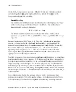
Sources of instrument noise in the MultiClamp 700B.
•
See also Feedback Resistor, Filters, Grounding and Hum, Headstage, Power
Supply, Series Resistance Compensation.
Measurement of Noise
Noise is reported in two different ways in this manual.
•
Peak-to-peak (
p-p
) noise. This measure finds favor because it is easily
estimated from an oscilloscope and its meaning is intuitively obvious. A
disadvantage is that it is very insensitive to structure in the noise (
e.g.
different
frequency components). For this reason, it is most commonly used for
quantifying “white” noise. (See Chapter 5,
FILTERS
.)
•
Root-mean-square (
rms
) noise. This is essentially the “standard deviation” of
the noise and can be calculated using a computer or an electronic circuit
designed for this purpose. For white noise, the rms noise is approximately one-
sixth the peak-to-peak noise. The MultiClamp 700B Commander displays the
rms noise on the Membrane Current signal in V-Clamp mode after checking the
Irms checkbox below the meters. The measurement is made with a bandwidth
of 30 Hz to 5 kHz (4-pole Butterworth filter). See the table on page 92 in the
Feedback Resistor section for noise measurements using the CV-7 headstage.
When reporting measured noise, the bandwidth (
i.e.
filter cutoff frequency) must
always be stated.
Sources of Noise
Cell and Seal
V-Clamp:
The higher the resistance (
R
) and the smaller the capacitance (
C
)
between the interior of the electrode and ground, the smaller the current
noise. Thus, minimum noise is achieved for an isolated patch (large
R
,
small
C
) with a high seal resistance (large
R
). In whole-cell recordings
MultiClamp 700B Theory and Operation, Copyright 2005 Axon Instruments / Molecular Devices


