Tutorials
•
17
Tutorial 1 – Electrode in the Bath: Voltage Clamp
1. Switch on the MultiClamp 700B and run the MultiClamp 700B Commander by
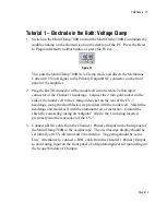
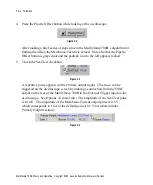
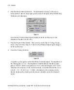
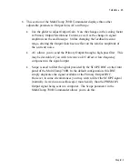
double-clicking on the shortcut icon on the desktop of the PC. Press the Reset
to Program Defaults toolbar button, or press the F6 key.
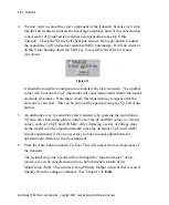
Figure 3.1
This puts the MultiClamp 700B in V-Clamp mode and directs the Membrane
Current (0.5V/nA) signal to the Primary Output BNC connector on the front
panel of the amplifier.
2. Plug the BATH connector of the model cell into the white Teflon input
connector of the Channel 1 headstage. Connect the 2 mm gold socket on the
side of the model cell to the 1 mm gold socket on the rear of the CV-7
headstage, using the short black wire provided with the model cell. Shield the
headstage and model cell with the aluminum foil or metal box. Ground the
shield by connecting (using an “alligator” clip) to the 1 mm plug inserted
previously into the rear socket of the CV-7.
3. Connect a BNC cable from the Channel 1 Primary Output on the front panel of
the MultiClamp 700B to the oscilloscope. The oscilloscope display should be
set initially at 0.5 V/division and 2 ms/division. Triggering should be set to
Line. Alternatively, connect a BNC cable from the Channel 1 Primary Output
to and Analog Input on the front panel of a Digidata digitizer for monitoring on
the Scope Window of Clampex.
Chapter 3

