22
•
Tutorials
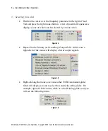
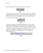
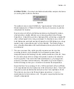
(Note the information provided under Experiment Type and Range in the Gains
panel.)
Figure 3.10
Select 50 G
Ω
feedback resistor and then close this panel.
4. Note that the noise trace on the oscilloscope is now about 150 mV
p-p
. However,
the Primary Output gain is now 0.05 V/pA, so the noise is 3 pA
p-p
, a 3-fold
reduction compared with before. This is still quite noisy for recording single-
channel currents of a few picoamps. To clearly see small currents, it is
necessary to filter the Primary Output.
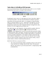
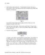
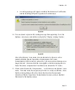
5. Locate the Primary Output section in the main window of the MultiClamp
700B Commander and position the mouse cursor over Bessel: 10 kHz. Using
the glider control (see Chapter 2) examine the effect of filtering the Primary
Output.
Figure 3.11
Note that with a filter setting of 2 kHz the peak-to-peak noise on Primary
Output is about 0.5 pA, which is adequate for most single-channel recording.
(See Chapter 4 for practical hints on how to reduce the noise further.)
MultiClamp 700B Theory and Operation, Copyright 2005 Axon Instruments / Molecular Devices

